|
|
Post by Marathonman on Sept 27, 2019 11:41:08 GMT -6
Good news, thanks to a small *donation* *(Thank You)* i was able to purchase a new slip ring for my brush holder rotor. so when it gets in next week i will begin to reassemble part G then test some time after that. the old one had to be cut off because it was warped and resigned on the shaft, DUH ! i was also able to purchase for a very cheap price on ebay a very nice breadboard so i can begin testing the code for the electronic switching of part G. even though i am working on the mechanical version i can still help in the electronic version to jump start that area. i have the help of the Arduino forum to streamline the ISP coding which when finished will be presented to the public to build an electronic version of part G as does two other builders in the electronic section. 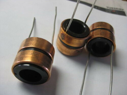 again thank you for the donation, i can now make some forward progress in the mechanical and electronic version thus posting pics of my progress. PS. the ID is 1/64 smaller then my shaft so i have to find a better way to take it down and not screw it up like the last one. Regards, Marathonman |
|
peter
New Member

Posts: 24
|
Post by peter on Sept 27, 2019 14:35:31 GMT -6
 This is my new design, looked at the design of other builders here, and came up with this one. 2 16 piece commutators for +(red) and feedback (Blue). All pieces of the first commutator are interconnected, effectively making this a slip-ring. The whole thing is 10 cm long and has a radius of 4 cm. very small. the main shaft is hollow and mounted on 2 roller bearings, wiring goes through the schaft. 4 double carbon brush holders (alieexpress) little flywheel is 10mm thick and holds the 2 other carbon brush holders. At the end a 32 piece commutator to feed part G |
|
|
|
Post by cornboy on Sept 27, 2019 16:17:51 GMT -6
Hey Peter, looks great, just curious, how do the main feed brushes, mounted on the alloy flywheel, run on the large commutator?
Best regards, Cornboy.  |
|
peter
New Member
Posts: 24
|
Post by peter on Sept 28, 2019 5:07:37 GMT -6
They run on the inside. Brush holders A and B remain static. The 32 part commutator also remains static.These have to be interconnected as to get 16 outputs to part G 'Knight rider' style The frame which holds brushes A, B, and the 2 bearings is not drawn.   Attachments:
|
|
|
|
Post by Marathonman on Sept 28, 2019 8:40:52 GMT -6
That's some beautiful 3D work Peter. what program did you use.? i have never used one before so i know nothing about 3D software.
I am having problems finding another motor for my rotor. it has to be a shaft diam of 6 mm so i am limited. the old BEI junk i had doesn't even have bearings which is why it failed. i might of found one on ebay but wow, what a price. it does have bearings though and a top speed of 5000 unloaded.
only time will tell.
MM
|
|
|
|
Post by cornboy on Sept 28, 2019 16:01:28 GMT -6
Nice cads Peter, it has been my experience so far that the slightest movement or chatter, or out of round, will cause sparking, so i suggest when you build it that you shorten the design as much as possible, and have the shaft come right through the other side of the large comm to sit in a bearing in an end plate that is fixed to the large comm. The shaft needs to be as large diameter as possible, especially if hollow.
These comms need to be as solid and stable as electric motor setups.
Hope this helps, Regards Cornboy. |
|
|
|
Post by Marathonman on Sept 28, 2019 23:58:27 GMT -6
Absolutely, i couldn't agree with you more.
i have the motor at one end for support and a bearing at the other so very smooth. i would venture to say it is a must to have support at both ends or as close as possible. the new motor i want has real bearings at both ends for longevity.
my shaft on my rotor is at 17.5 mm and i wish it was bigger but parts are hard to find at higher diameters and i do not have the proper tools to build my own.
Very good advice Cornboy.
MM
|
|
|
|
Post by Marathonman on Sept 29, 2019 16:00:43 GMT -6
I have never felt to comfortable with the clips i used for securing the bearing to the bottom of the plate on part G so i am in the midst of changing the design. this new design was attained from a Spark Fun part with some minor changes to the lip to secure the bearing in a cup like fashion where the bearing can sit in being bolted to the bottom of part G's mid Aluminum plate with no movement or vibration what so ever. it is not like i had any before i just feel this is a much better approach for longevity. with the two real front and rear bearing supports the new motor will have plus this will completely secure my rotor to the max. Edit;unfortunately i can NOT get Emachineshop to act right as it freaks out every time i try to extent it into a cup to hold the bearing in place. the video below has a flat face which is screwed to the bottom of an Aluminum plate to hold the bearing into place. it is this face/end that i need to insert the bearing resting on the opposite end plate that has a hole in it to allow the shaft to go through. this lip is what will bold the bearing in place yet i can not get it do it to save my life. it is basically a cup with a hole to allow the shaft to go through which the cup is attached to the 1/8 inch plate yet one piece which will use CNC to manufacture. that way once it is screwed into place the bearing can not move, vibrate ect...ect. anyone have any suggestions.  or should i just contact a CNC place to explain. part was rotated in Free Cad then screen capture by OBS Studio. Regards, MM |
|
peter
New Member
Posts: 24
|
Post by peter on Sept 30, 2019 0:46:51 GMT -6
That's some beautiful 3D work Peter. what program did you use.? i have never used one before so i know nothing about 3D software. I am having problems finding another motor for my rotor. it has to be a shaft diam of 6 mm so i am limited. the old BEI junk i had doesn't even have bearings which is why it failed. i might of found one on ebay but wow, what a price. it does have bearings though and a top speed of 5000 unloaded. only time will tell. MM Thanks MM, Im using Blender. It's freeware so that's very nice. good to hear you're up and running again.. |
|
|
|
Post by Marathonman on Sept 30, 2019 9:59:43 GMT -6
Peter;
I was wondering if you have the time could you fix the Cad i have of the part in the video. i have the dimensions i need but since i am VERY new to Cad software i am lost in Blender. what i need is a lip on the protruding side to catch and hold the bearing in place which is a basic hole for the shaft to go through. the bearing is inserted on the flat side as to lock it in when screwed to the bottom of the mid plate. the lip sticks out just shy of inner shaft contact to not interfere with rotation. that way i can have have the part CNC'ed to my liking.
PS. i see where Blender has a lot more backing funding now as they have improved soooo much. expect great things coming from blender in the future. even now it has been revampted to a more streamlined work flow.
PSPS. not up and running just some forward momentum.
any help would be highly appreciated.
Regards,
Marathonman
|
|
|
|
Post by creasysee on Sept 30, 2019 14:35:49 GMT -6
The picture shows a rear side of the commutator (isn't finished yet). Output leads from half of the pins will go to the winding of the part G. The other half connects with the first half. Wire 2mm dia (AWG12) 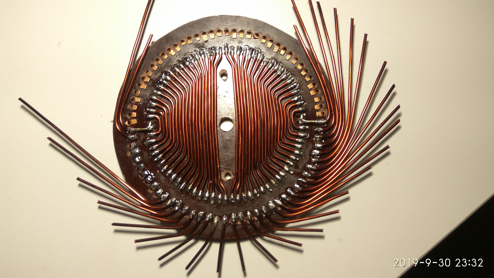 Regards, creasysee |
|
|
|
Post by cornboy on Sept 30, 2019 14:54:12 GMT -6
Nice Job Creasysee, very neat, are you epoxying and machining the contact side?, would love to see pic when finished.
Good Job, Cornboy. |
|
|
|
Post by creasysee on Sept 30, 2019 15:36:26 GMT -6
Nice Job Creasysee, very neat, are you epoxying and machining the contact side?, would love to see pic when finished. Thank you, Сornboy! Sure, I plan to fill the contacts with epoxy and surface finish on a lathe. Regards, creasysee |
|
|
|
Post by Marathonman on Sept 30, 2019 16:59:37 GMT -6
Very nice work Creasysee, skillfully executed.
i am almost afraid it is going to jump out the screen onto my face like Aliens and shove a tube down my throat. ha !
you can always tell the work from old schools like us from the neatness of our work. newer generation do some F_ed up shit.
just wish i had access to the good tool and machinery, love the toys..
Nicely done can't wait to see some action.
MM
|
|
|
|
Post by Marathonman on Oct 2, 2019 22:40:11 GMT -6
Thanks to Peter, he was able to modify my part to my specs which basically turned a joe blow SF bearing holder to a real bearing holder that completely holds the bearing in place . it drops in from the flat face then the flat face gets bolted to the bottom of my mid plate on part G never to move again. this way i have two motor bearings on one end and one large bearing on the rotor shaft on the other end. no more clips. it also serves as the bolts to hold the brush bars in place. also if the part is to expensive to make i can 3D print it in a very strong material like Carbon Fiber filament or there of. Thanks again Peter, well done. MM 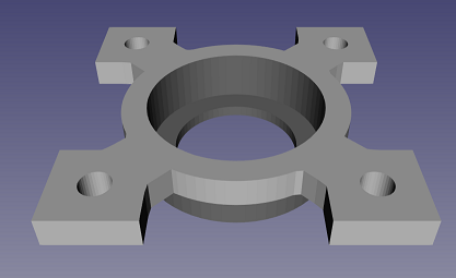 |
|


 or should i just contact a CNC place to explain.
