|
|
Post by Marathonman on Dec 4, 2019 14:47:14 GMT -6
I have been in contact with Alejandro Polanco which actually came across the Figuera patent 20 years ago in Spain. he is in the research of History of Science and Technology in Spain. he then came across a device from 1882 that he said was similar to the Figuera device but after further review it seems to me it is closer to the 1932 Coutier Device except it has core in a circle and many of them. as i studied the attached picture i added the thick black letters to identify the parts of the system. it seams to me that the inputs (primaries) are series and the outputs (secondaries) are paralleled into two circular bus bars. this is more similar to this device then that of the Figuera device with the exception being the whole device is circular instead of separate cores like Coutier did. in my review i did find one mistake in the drawing. the unit to the left has an "R" at 10:30 on a clock which is an output core shown connected wrong as it is connected to the input in series which according to the right drawing is wrong, unless it powers the one on the right through the controller which doesn't look like it. Very interesting just the same. Regards, Marathonman  |
|
emilp
New Member

Posts: 19
|
Post by emilp on Dec 5, 2019 7:32:08 GMT -6
I was 2-3 weeks busy and could not handle the project in the meantime. I also need to build a stronger winding device for thicker wire.
Ok, I studied the scheme a little, the mistake at 10:30 on the left is clear (on the right is ok).
Is there any information regarding the number of primary / secondary turns or the amplification factor, voltages, etc.?
Yes, at first glance it seems that the primary coils (15 pcs) are connected in series and the secondary ones in parallel (another 15 pcs).
It's strange that all the coils have the same section, a kind of toroid-shaped core.
More to be studied ...
All the best.
EmilP
|
|
|
|
Post by Marathonman on Dec 5, 2019 9:54:03 GMT -6
The strange part is the patent is hand written which is very hard to translate with excellent drawings which is 180 degrees from the Figuera patent which has excellent explanation with lousy drawings. this device drawing is excellent as i have blown it up very huge with very good detail. i have the description but it needs to be translated if anyone is up for the challenge....WE NEED A TRANSLATOR ! maybe we need to move this to it's own thread  ?? Regards, Marathonman |
|
peter
New Member
Posts: 24
|
Post by peter on Dec 5, 2019 11:24:41 GMT -6
Very nice drawings indeed. Nice that you have this in a bigger size, because i downloaded this, but it was unreadable. Would love to see the big one .  kind regards. Peter |
|
|
|
Post by Marathonman on Dec 5, 2019 20:17:31 GMT -6
I downloaded the pic because i did not understand how it could be blurry but the resolution is not that good when downloading for some reason. since detail is lost i will add direct link so you can get the full 12.5 mb. Postimage has a 12 mb limit so a direct link is the best. here is the link. 1882 Patent i have a 42 inch HD screen and it looks beautiful for 137 years old at 4724 x 4370 which is very large file. enjoy. this patent was found in Madrid so that makes me wonder that if this is in such good shape then how on earth did the Figuera patent supposedly get so damaged. i say BS the other papers of the patent were purposely taken. Regards, Marathonman |
|
peter
New Member
Posts: 24
|
Post by peter on Dec 6, 2019 2:05:37 GMT -6
WOW... Thank you MM. Very cool..
|
|
|
|
Post by Marathonman on Dec 6, 2019 10:04:14 GMT -6
I would still suggest continuing with the Coutier device as it is much more simple to build.
the 1882 device is very intricate and will take a very long time to build and much more costly.
still a fantastic looking device just the same.
Regards,
Marathonman
|
|
|
|
Post by hermes on Dec 9, 2019 17:32:28 GMT -6
This video is NOT a Bi-toroid Transformer. It is the Coutier 1932 with a primary and two secondaries. I had the same material as in the video at home. I built it and measure it. It had four layers of copper wire as the primary, but 5 layers of copper wire on the secondaries. I thought by using more turns on the secondaries I could rectify the outputs and lose 1V2 over the rectifying diodes and loop it to a 5-20 khz oscillator. The cores in the video are ferritecores from an old TV-Set. When measuring the output I was very dissapointed to find the voltage loaded on the secondaries was only half of the input voltage and I measured both the input and output voltage*ampere and found the coutier transformer was less then 100% effective. Try to build the coutier transformer inverted. Double the size of the secondaries core compared to primary core. I have asked for a spanish to english translator at groups.io/g/EVGRAY you are invited to join. Write: "I just joined" in the message field. Best Wishes, Hermes |
|
|
|
Post by Marathonman on Dec 9, 2019 23:49:16 GMT -6
I really do not see how you people deviate so far from patents and wonder why your device fails then turn around and deviate even farther. good god i give up, it's like talking to the wall anyways.
The frickin video says right on it BI-TOROID TRANSFORMER.?? what have you been smoking??
the model shown is no where near the specs of the Coutier device as is the cores used.
EDIT;
the amount of flux needed for the six secondaries is matched by the larger primary core. if you invert you will get almost nothing out which shows me you know nothing about this device or magnetic fields or the proper flux needed for emf generation. you did the same thing to the Figuera device on other sites and i do not need you on this site spreading false information that are physically incapable of producing anything.
i will also add that when posting, referring to other sites and works are permitted but to come on MY site and advertise for another site is wrong and do it again and i will ban you and your false information.
do you understand that.? it's bad enough i have gutless idiots like Seead and others bashing me on other sites for no other reason then out of spite and jealousy which are to stupid to understand this device in the first place let alone actually do any research on the device. then you have the balls to come on MY site and spread false information.
only warning, do it again and i will permanently ban you.
MM
|
|
|
|
Post by Marathonman on Dec 16, 2019 14:46:26 GMT -6
So back on track, how is it going Emil have you made any forward progress.??
the cores are pretty much straight forward as we should all know the surrounding cores cross section combined area should match that of the center core with a little headroom. we also know that each coil set has the same winding count as it's center core in each group as a one to one ratio which are paralleled into the next coil/core group. so then it is logical thicker wire is used as current ramps up and less amper turns per core /coil group.
so this leaves us with the feedback isolation portion of the circuit and the actual oscillation or excitement of the original coil/core. if one so chooses to use mechanical oscillation as in the original patent then the use of a Mallory oscillator type setup is deployed. if electronic deployment is used then one could use a pure sine wave inverter or something similar to get the excitation and the use of an isolation transformer. my suggestion would be to use a toroid transformer for the isolation as toroid's are much more efficient then say a microwave transformer with square corners.
of course there will be some trial and error involved but that is the least expensive part as the acquiring of the cores and excitation/isolation are the biggest investment.
regards,
Marathonman
|
|
emilp
New Member
Posts: 19
|
Post by emilp on Dec 18, 2019 5:40:59 GMT -6
I have two contracts in working order that I have to finalize until Christmas, so I have allocated all the time in this regard, including on weekends. As I said above I have to rebuild my winding device. I took a counter with a magnetic sensor like this: www.ebay.com/itm/ZX-5A-Magnetic-Induction-Digital-Display-Electronic-Counter-Punching-Machine-/262974118391A neodymium magnet passes in front of the sensor and sends a pulse to the counter (it has 2 buttons: RESET and SUSPEND, maximum 20 pulses / sec). So it is contactless! The magnet holds the handle if it is iron. I thought it was useful information for other builders, especially since everything is powered by a 1.5v battery that is in the counter and is very cheap. I bought another cutting device to cut the transformers more easily. I have calculated several ways to cut them, so that I do not have losses and to have as few cuts as possible. I haven't decided yet. Do you have any suggestions for cutting MOTs? I have the workshop outside in a covered veranda, but it's quite cold now. I'll see how I do it. All the best. EmilP |
|
|
|
Post by Marathonman on Dec 18, 2019 8:48:21 GMT -6
Yes that looks like a good idea with that counter, very low power indeed. it will be difficult cutting Mot's as a whole but it can be done. i think the whole key is to just take your time cutting. the bast way i know to cut them is with a metal band saw. it can be cut this way without clamps as the cutting force is always down but supported underneath. the next would be to clamp it or in vice and clamp then cut between those two. or a more time consuming step is to completely disassemble them and cut with sheers then epoxy back together like i do with my cores. to take them apart to start the weld below has to be cut, granted some material is lost but somethings are unavoidable. 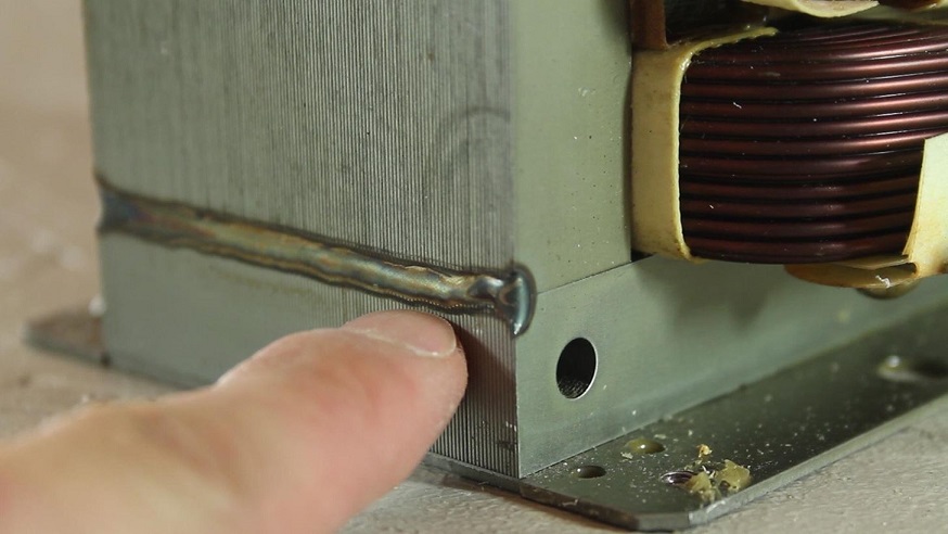 once the weld is cut the core can be taken apart. as i said you can cut at the lines shown or take it completely apart. just take your time as it is quite easy to flare or bend the laminations. cutting across the width of the lamination is best as cutting across the depth will flare or bend them. 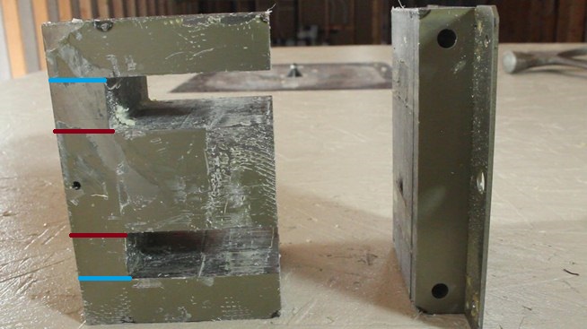 another thing is pay attention to the grain of the metal as the above lamination has the grain going side to side and the end piece is up and down. there is no real easy way about this so all i can say is dive in the best way you can think of but just do not get in a hurry. even if you do slightly bend the laminations you can always epoxy then put it in a clamp or vice over night. when estimating your cores you can weigh the bare core then estimate the lbs per va rating. as an example say i had an 1,100 watt core and it weighed 10 lbs then it would have a va rating of 110 per lb of lamination which will help with the calculations of the output of each core. each core should weigh the same or as close as possible. Mot's are a pain in the backside but it is completely doable for sure. remember even if the Mots are of a different rating or manufacture they generally use the same material for all mots so the concentration of the weight is more important then the material it's self. remember folks Mot's can be used for the Figuera device also and the 1882 device i have posted. Regards, Marathonman |
|
|
|
Post by Marathonman on Dec 30, 2019 12:40:10 GMT -6
I have been studying this device and i have come to some realizations of some facts concerning the cores. the six outer cores in the first group must be able to output 120 watts without saturation so the cores have to be around 150 va or so. that means the center core must be able to sustain at least 750 va or watts of flux in order to support all six smaller cores.
in the second group of cores the six outer cores must be able to sustain at least 750 va or watts of flux to attain the us 120 volts 6 amp of output. this means the center core must output at least 4,400 va of flux at 120 volts and 6 amp of current. this is a substantially larger of a core then i originally expected.
in the third group of cores the six surrounding cores must be able to handle at least 4,400 va or watts of flux each at 36 amp and 120 volts. what this means is the center core must be able to output 26,000 va of flux in order to sustain all six outer cores. 26,000 va core is a very huge core and will be very expensive.
i think my calculations are correct but just in case i will want feed back from people concerning this proposal. it makes a lot of sense that each core group will of course be larger in order to sustain the required outputs.
regards,
Marathonman
|
|
emilp
New Member
Posts: 19
|
Post by emilp on Jan 2, 2020 10:36:26 GMT -6
First of all, I wish you a "Happy New Year!" and I wish you that 2020 will be a better year, full of joy, success and health!
The observations you made above are very correct. The loss of magnetic flux between the central core and the satellites (20-30%) must also be considered.
When the satellites are short-circuited for a few seconds, the core must not saturate. If the core becomes saturated in secondary the current is zero. So I can test if there is enough iron core.
All the best.
EmilP
|
|
|
|
Post by Marathonman on Jan 6, 2020 10:40:45 GMT -6
Thank you for the feed back Emil.
I think the saturation will amount to a flattened sine wave as it attenuates the signal chopping off the rounded peak. your losses might be right but then one must consider the flux is traveling in that direction anyways to get to the South field. iron core will attract or absorb the flux as an easier path of travel. you seem to have a very good grasp on the reality of things Emil and i am very confident you will succeed in your build. the world needs more people like us to question the so called authorities and their BS controlling ways.
I had a chance to acquire 5 or 6 microwave ovens a day or two ago but i have no place to store them. i am so mad i had to pass it up as i know they would of come in handy down the road with other devices. once i get situated i will not ever pass up acquiring cores in the future.
the reason i posted the 1882 device is it works on the very same principal as the Coutier device only in a continuous core.
Regards,
Marathonman
|
|


 ??
??
