|
|
Post by Marathonman on Nov 3, 2019 11:43:06 GMT -6
After further review it seems to me that because you changed the sequence of primaries and part G it will no longer act as an amplifier of the three potential sources. by changing the primaries in relation to part G, the primaries no longer add it's released potential directly into part G to aide in the amplification process. this will negate the ability to forward bias the rising primaries which is needed to raise the current flow offsetting the reducing primary reduced potential which reduces the overall pressure between the two opposing primaries.
Part G is the sole power supply after the starting is removed, this was and is achieved by all three potentials converging in part G (amplification) which is then circulated around the system to the primaries which acts accordingly to these increased and combined potential.
there is no way to tell if the reordering of parts completely negates the ability to self sustain unless it is actually build. on first glance i would say no, it will not work but then again electricity does have it's own way of doing things in the long run.
obviously building and testing will have to be done to see the final outcome as this is most definitely a deviation from the Figuera device.
again good luck with this setup and i wish you well.
Regards,
Marathonman
|
|
cheors
Junior Member

Posts: 33
|
Post by cheors on Nov 3, 2019 14:32:26 GMT -6
Here is how i understand the equivalent circuitry and the power supply polarity modification i have made. PART G and the 2 primaries are still serially connected. The switches (MOSFET ) still increase or reduce the inductance values.
Do you agree with this schematic ?
Ok we will see with real tests.
Best regards
|
|
|
|
Post by Marathonman on Nov 3, 2019 15:27:31 GMT -6
Both schematics you show are negative and ground at either end.
what you are somehow overlooking is the amplification that is taking place in part G because of the three potential in the order Figuera put them in which is not taking place in your circuit.
as you say, tests will reveal all and i do hope it works but the chances are it might be not be what you are here to achieve.
Regards,
Marathonman
|
|
cheors
Junior Member
Posts: 33
|
Post by cheors on Nov 3, 2019 16:11:56 GMT -6
Please, could you quickly draw the good schematic ( something similar to the one i previouly tried to show) ?
Thanks
|
|
|
|
Post by Marathonman on Nov 3, 2019 23:48:13 GMT -6
Cheors; There is nothing wrong with your schematic skills, what is wrong is you trying to rearrange the items in the Figuera device or polarities and think they will work. i for one think this is to much of a gamble for all your time, effort, money ect.. to waste on a whim knowing the whim is a deviation from the patent, which i might add, shows the arrangement quite clearly. Figuera did this arrangement for a reason, and that would be because part G becomes the power supply once the starting is removed. the primaries release it's potential into part G to be added with part G's released potential like series batteries and the secondary feedback potential all to forward bias the rising primaries which in essence acts in the same regards as an amplifier. i am just telling you this because i have see many, many people do the same thing over the last 6 years and ALL of them ended the same way because they deviated from the patent. some a little, some very far, but all of them ended in failure because no one wanted to listen to reasoning and common sense. if you feel like you want to test it then by all means test it and find out for yourself. this is how all people learn as well as myself included and is why it is called research. the patent is not going no where so please do what you have to do as a researcher. i for one am sticking as close to the patent as i possibly can and that is with the positive on top and the negative on bottom of your schematic as is mine. PS. i did not see you changed it until i downloaded the pic on my big screen. easy to see on 48 inch monitor for computer. Regards, Marathonman 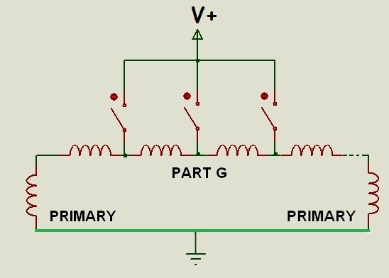 |
|
|
|
Post by Admin on Nov 4, 2019 9:42:16 GMT -6
Congratulations, we have a new member "Hermes" that have joined the ranks.
glad you can make it and welcome aboard.
together we can make a difference in the world.
|
|
|
|
Post by Marathonman on Nov 6, 2019 16:21:48 GMT -6
I am curious if anyone has used the Nexperia NPIC6C4894DY shift register. it seems to be a good ic with an output at 100 ma continuous each - 250 ma max per output, absolute 1250 ma per ic. the reason i ask is it has 12 outputs per ic which will reduce chip count. with that amount of current it can run quite a few things and even the split signal for the secondary brush circuitry.
MM
|
|
peter
New Member

Posts: 24
|
Post by peter on Feb 20, 2020 7:29:41 GMT -6
Hi Builders. I've got a question for you all. Instead of the rotating brush. could'nt we use something like this to get the correct signals to the primaries.?? 1 primary and 4 secondarys. 2 secondarys to provide DC offset, and 2 secondarys ( 1CW and 1 CCW) to get the 180 degree phase shift in the AC signal in there. Also thinking of multiple taps in the secondarys to change the amount of DC and AC with a flick of a selector switch ![]() Figuera_001.pdf Figuera_001.pdf (672.26 KB) |
|
|
|
Post by Marathonman on Feb 20, 2020 8:12:52 GMT -6
Peter;
The use of one primary will not compress the field lines to match that of a standard generator and the use of one core which puts your setup in the transformer category. also putting the primary on the same core as the secondary induced eddy currents in the primary reducing the magnetic intensity of the primary.
the whole purpose of the separation is the primary magnetic field resides outside of the core where all the action takes place within the area occupied by the secondary and the collision point of the two primary magnetic fields.
with the Figuera setup the secondaries can be dead shorted and will not effect the primaries as all the action resides outside of their core and opposing at that which will not magnetically link to each other like that of your setup and a transformer putting the draining load directly on the supply.
i hope this makes some sense.
Regards,
Marathonman
|
|
peter
New Member
Posts: 24
|
Post by peter on Feb 20, 2020 8:51:23 GMT -6
Hi MM, Thank for the answer, but this schematic was purely to provide correct signals. It's indeed a standard transformer, but it sets up the needed 180 degree phase shift, and adds the DC offset, which then could be fed to the primaries. I added the primaries and the sandwiched secondarys (Y) into the schematic  I know the first transformer is never going to be 100% efficient, but if my 7 triplets give me a 1000 Watts, and the transformer costs me 200 watts, I'll be happy |
|
Deleted
Deleted Member
Posts: 0
|
Post by Deleted on Feb 20, 2020 16:35:59 GMT -6
removed by Skyrob
|
|
|
|
Post by Marathonman on Feb 21, 2020 8:11:27 GMT -6
We are building to the Patent of 1908 and anything other then that i will not dwell on. trying to modify the original patent before even building and understanding the original is not very wise to say the least. i do not do crapshoot's that will end in failure.
i must remind people this thread is for electronic switching.
Regards,
Marathonman
|
|
|
|
Post by creasysee on Feb 21, 2020 13:14:37 GMT -6
We have the General Discussion board for free discussions. Let us know if you cannot create some "My custom device and what I think about it" thread there. |
|
|
|
Post by Marathonman on Aug 22, 2020 14:07:14 GMT -6
Hello all,
I have a concern regarding the use of a high side driver in the Figuera device switching part G taps. my concern is will the high side elevated signal to the NPN or IGBT's from the boot strap cap cause an elevated signal in the line which is circulated within the exciting side of the system. this will be not a problem when dealing with an NPN/PNP switching scenario where the NPN or even a high power opto isolator switches on the power PNP.
since i am not at this point yet i was wondering if anyone has tested this scenario and what conclusions have you gathered. i have a circuit board made but it is an NPN/PNP set up and does not utilize the 100 IGBT's i already acquired a year ago. i know i need to test this scenario out but i was hoping someone has some input on this testing phase of part G. i found a cheap high side driver at Mouser @ 60 cents per 100 which is the FAN73611 single high side driver.
also since the switching will be in the 300 microsecond range will the boot strap cap keep the tap activated for make before break scenario.
Regards,
Marathonman
|
|
|
|
Post by Marathonman on Aug 24, 2020 14:34:13 GMT -6
Please be mindful of the fact that this device can be switched with electronics but not electronics alone. they have to be used to switch part G as part G can not be replaced. part G controls the current flow and the storing and releasing of potential. in the Figuera tech thread i have posted the reasons as to why part G can not be replaced with electronics exclusively. you can not interfere with part G's operations or the device will not work plain and simple.
if you still feel you need to go this route then all i can say is good luck.
Regards,
Marathonman
|
|


