|
|
Post by Marathonman on Nov 30, 2021 16:30:27 GMT -6
I have been tinkering with the program i posted and researching DWF DigitalWriteFast. it seems that DWF sits at the high teen ns as in 17 to 20 ns. this is a well within parameters in the switching of part G taps. of course direct port manipulation would give slightly better results but DWF does the job just fine since we are or will be switching near 300 us.
so i changed DW to DWF and used a 1 us delay which seems to be just great for my use. all the hardware i have so far designed have exceeded my expectation in the switching of the taps with the exception of the Teensy 4.1. i have removed the support off of the board and for now will concentrate on the Teensy 4.0 which works just great. this is just fine as the first 14 pins are the same with most of them anyways
Regards,
Marathonman
|
|
|
|
Post by Marathonman on Dec 5, 2021 19:53:50 GMT -6
My past test on a two channel high side driver circuit did not end very well. one of the high side driver literally melted the ground on the low side of the chip in an arching fashion. since the voltage was well with in the parameters of the ic chip even accounting for the voltage gain in the system. i still have not figured out what went wrong.
if anyone has some input as to why this happened please by all means chime in. test parameters were at 100 volts yet the chip is rated for 600 and the input is supposed to be isolated from the high side.
Regards,
Marathonman
|
|
|
|
Post by Marathonman on Jan 2, 2022 15:18:08 GMT -6
I actually have changed the Program to DigitalWritefast and used 10 ns delay and it seems to be a perfect match. also with the three channels tied to each other on the ends i have successfully mimicked the mechanical brush rotation to the letter with that and shifting two channels at a time for make before break scenario. no other program i am aware at this moment can do this so closely mimicking the mechanical rotating brush.
remember the active inductor controller Figuera used was a straight wired inductor showing only the brush rotation in the patent and not the rest of the inductor or core which has mislead many, many researchers in the past. but even with that misleading drawing in the patent one must realize that the ends are on for a longer time then that of the middle brush connections not to mention make before break making contact with two at a time.
with this discovery you must realize that the delay of being on for a longer time has the effect of inductive roll off of the primary inducers. this gives the nice rounded sine wave of the secondary output as the bloch wall or compression zone is shifted to the other side repeating continuously. this inductive roll off of course is at the top and bottom of the secondary output wave form.
this is why i have spent so much time in studying the inductor controller and it's action then incorporating this into the electronic switching. there are to many researchers out there trying to (in their mind) upgrade or altering the patent thinking it is going to work without completely understanding the patent or device. failure in immninent, then comes the statement ( It doesn't work).
this is why i am trying to stick as close to the paten as i can without alterations and hopefully leading to a successful operating device.
Regards,
Marathonman
|
|
|
|
Post by Marathonman on Jan 2, 2022 16:17:02 GMT -6
// This sketch controls multiple 74HC595 shift registers in cascade to electronically control Figuera's active inductor
// controller by switching on taps located on part G connected to transistors in a "Make Before Break" scenario. by changing
// tap locations continuously changes inductance which controls current flow of the primaries.
// this sketch utilizes timing overlap to eliminate back Bemf or Cemf that would occur with single on off tap. it mimics
// the brush rotation of a mechanical rotating brush thus creates a continuous increase/decrease current through the primaries.
// this sketch is distributed freely but if you use this program then post build on line give credit where credit is
// due and not claim as your own design.
// to adapt to your build change pin numbers, delay time.
// developed for the electronic Figuera community by (DL)aka Marathonman with all technical help and coding of PaulRB on Arduiono.cc
// Forum.
// Mosi to DS in pin 14 on 74HC595
// SCK to Seial Clock SHCk Shift Clock pin 11 on 74HC595
// SS, CS or any latch pin declared output to STCK latch pin 12 on 74HC595
#include <SPI.h>
unsigned long long int registerBuffer = 0b11;
byte shiftPos = 0;
bool shiftingLeft = true;
unsigned long long int lastUpdate;
const unsigned long long updatePeriod = 100000ULL; // change this microseconds figure to what you need for program speed.
const byte latchPin = 10; // this can be changed to what ever latch pin you want.
void setup() {
Serial.begin(115200); // use you SPI pins found on all Arduino's. coding will automatically take care of the rest if SPI0 pins
// used.Mosi0,SCk0 Ect...
SPI.begin();
SPI.beginTransaction(SPISettings(1000000, MSBFIRST, SPI_MODE0));
pinMode(latchPin, OUTPUT); // pinMode can be changed to direct port manipulation (Faster)if port is known then that of digital
// read/wright. but will be chip specific with DPM.
}
void loop() {
if (micros() - lastUpdate > updatePeriod) { //Is it time to update the registers?
lastUpdate = micros(); //Shift the register left or right
if (shiftingLeft) {
registerBuffer <<= 1; //Shift 1 place to left
if (++shiftPos == 62 // < add how ever many pins or taps on part G you have up to unsigned long long of 64 buffer minus 1.
//remember 0 to 63 = 64 pins bytes.
) shiftingLeft = false; //Time to switch direction?
}
else {
registerBuffer >>= 1; //Shift 1 place to right
if (--shiftPos == 0) shiftingLeft = true; //Time to switch direction?
}
unsigned long long int temp = registerBuffer; //Take a copy of the buffer
SPI.transfer (&temp, 8); //Send the buffer to the registers // This must match your Shift Register count 1 through 8
digitalWriteFast (latchPin, HIGH); //Latch the updated values into the register's output pins
delayNanoseconds (10);
digitalWriteFast (latchPin, LOW);
}
}
The above code was changed to DWF because of the low ns switching and the delay at the end was further reduced to 10 nanoseconds to minimize any such program delays. program run great on Teensy 4.0 but if you notice line "if (++shiftPos == 62" apparently the inadvertent shifting causes two bytes to be shifted at a time instead of one so i had to change this number to 62 in order for the program to shift properly. this is something i forgot to add this info many months ago when i posted this code. this is actually great because it shifts two at a time causing make before break just like the brush rotation.
just remember that the shift register IC count 1 through 8 must be annotated here in the program "SPI.transfer (&temp, 8);" of it will not shift correctly. so if you are using 6 shift registers it must be reflected there as that effects the register buffer count.
EDIT; Can you image 34 actual lines of code do all this . Make-Before-Break Shifting two bits at a time and in hardware three channels tied together for the inductive roll off.
Regards,
Marathonman
|
|
|
|
Post by Marathonman on Jan 10, 2022 21:31:30 GMT -6
I am currently looking for a suitable high side drive replacement for the electronic switching. i did find a good one but Lousy Infineon and other suppliers want a hundred plus min order. totally out of the question.
i am still looking and want to start the electronic testing again.
Regards,
Marathonman
|
|
|
|
Post by Marathonman on Jan 12, 2022 4:10:29 GMT -6
Found a good driver and ordered 4 ic plus supported resistors and capacitors. i am in the process of demo board design to evaluate the driver circuit. the mosfet/igbt driver is completely isolated from low to high side through Data transfer across the isolation barrier by Coreless Transformer Technology. that means this driver can be attached directly to an MCU ie.. 3.3 - 5v Arduino if needed. I am running the logic side at 5 volts and the high side at 15 volts so it will connect right up to my awesome Teensy shift register board. I will be testing the SQP10250E,SUP10250E both GE3 TO-220 Mosfets and the original IGBT's i bought a few years ago which this driver is perfect for.....I hope  Regards, Marathonman |
|
|
|
Post by Marathonman on Jan 12, 2022 11:08:50 GMT -6
I think i know why my previous two channel driver board test board blew out the ground. according to other manufactures of high side drivers ic's there is suppose to be a copper pore off of that pin to dissipate heat from current flow. the currant driver i am using says NOTHING of this what so ever. so along with the new drivers i bought (which are far better, I hope) i am still going to redesign it also accounting for the heat produced. then i will test both side by side. if they succeed then i will chose the cheaper of the two.
Since Mouser is 2 1/2 hrs away i get two day shipping so it is being shipped today and the new test board designs will be done tonight but since some crazy China holiday for a month i will not get them till next month unless i get osh park to do it which i do not like them.
Regards,
Marathonman
|
|
|
|
Post by Marathonman on Jan 27, 2022 12:05:15 GMT -6
I was just reviewing creasese's picture of his electronic art G and I noticed that the taps on his core were more on one side compared to the other and this will cause an imbalance of flux between the primaries.
when building device every single piece has to be balanced exactly. that is each primary has to be exact copies of each other ie... same weight, same winding count ect, ect which produce the exact intense magnetic fields. this also includes part G which is very important aspect of the whole device. It is my understanding that if balance between the primaries is not maintained the output will plummet to the lowest pressure between the electromagnets. the whole idea is to compress the field lines between the two sets then maintain that pressure while shifting the collision point from gap to gap only, no more no less.
each time you shift the collision point you are essentially filling the secondary with opposite flux that is circling in the opposite direction essentially fulfilling the exact requirements for generating EMF as your standard four pole rotating generator. this is a very important aspect of this device that is being HIGHLY overlooked.
please remember this is a stationary generator NOT a transformer and as such when the parameters are right the EMF generated will surpass the initial starting supply considerably suppressing the starting power as it is no longer needed. the device once started preserves the excitation potential through the storing and releasing of potential in part G and the primaries. once pressure in the excitation side is brought up to running conditions the secondary feed back maintains that excitation pressure replacing slight losses inherent in all of mans devices as our understanding of the universe is extremely limited at best. nothing in this device is wasted except for possibly the end of the electromagnet poles not being used. i am sure in the future a device can be built in a toroidal type shape preserving all the flux from both ends similar to the 1882 device i have posted. but until that time has come to pass i have to concentrate on this device first getting it up and running, then and only then will i move to make advancements in efficiency and EMF production.
another note to remember is when building your primaries each essentially produce half the flux required for the full output as you are using two electromagnets to compress the field lines to match that of a standard geny. also do not forget the added flux of each primary accounting to the gap between then and the long return path to the south pole. this required a stronger electromagnet to bridge the gap or to push the flux further.
this goes for the mechanical as well as the electronic version.
Regards,
Marahonman
|
|
|
|
Post by Marathonman on Feb 7, 2022 13:49:36 GMT -6
In the graph below which is just like the original patent except the original patent does NOT show the whole core specifically just the brush rotation ans worded as such. in this graph i have outlined the on time for the ends and one of the contacts in the middle. as you can plainly see the ends are on considerably longer then the ones in the middle. the ends are like four to five times longer as i have been saying for many years. also in the original patent it " SPECIFICALLY" says that the brush is making contact with two contacts at a time which is for a make before break scenario to allow the ongoing current rise and fall without any back emf collapse of the magnetic field in part G. in order to get the proper sine wave shape Figuera used his core design brush rotation to have the ends on for longer giving his output a nice sine wave shape. this equates to an inductive roll off because of this pause at the ends causing the induction to start to recede naturally giving it a nice rounded shape. as the brush continues it's rotation around the northern semi circle it naturally continues the reduction as the winding count increases to set N connection and decreases for set S connection. as my point exactly as i have been saying in order for the electronics to mimic this feature exactly as it applies, you have to account for this by allowing your electronics to have an on time of four to five times longer to allow for the inductive roll off just like the original patent. not only that but the make before break feature is also a ( MUST HAVE FEATURE) in your design. in my attempt to mimic the feature ( which is being highly overlooked) I incorporated the make before break and the ends on for four to five times longer to mimic the natural built in feature of the mechanical brush rotation into my electronic and coding output. my electronic switching mimics these features " EXACTLY" as i intended to do so from my years of study of this active inductor controller. as you build either the mechanical which has these features naturally built in or electronically, you must incorporate these into your design in order for it to function as the original patent. the blue lines represent the area of contact and the time spent on. 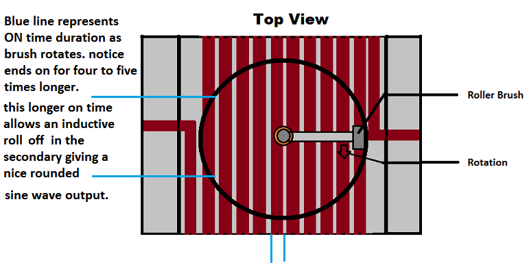 Regards, Marathonman |
|
|
|
Post by Marathonman on Feb 8, 2022 16:19:53 GMT -6
repost from mechanical with additions for electronic switching.
Here is a little tid bit to get your brain nice and fogged up.
the revolution of the Figuera device is at 3600 RPM or 60 Hz in the US which equates to 16.666 ms per revolution.
Lets say i have 150 winds on my part G either electronic or mechanical switching. you can not divide 16.666 ms by 150 to get the on time because the end winding's are on for 5 times longer then the ones in the middle.
so subtracting those two end winds and calculating them with additional time we are left with 148 winds. now add the on time for the ends 2x5 = 10. so 148 + 10 = 158.
now divide 16.666 by 158 you get .105481 ms or 105481 us.
148 winds x .105481 ms = 15.6111 ms
2 end winds @ 5 times longer = 10 x .105481 = 1.05481 ms
Total- 15.6111 ms + 1.05481 ms = 16.66591 ms = 1 revolution of either the brush or electronic switching on time.
of course i dropped the long numbers to the right going only five digits.
so the moral of the post is "IF" i had 150 winding's on part G each winding or taps in electronic switching will be on for .105481 ms or 105481 Microseconds with the ends on for .527495 ms or 527495 Microseconds each or both at 1.05481 ms .
this is the only way i could get the time right by doing it this way. now converting this above to electronic switching shift registers is another feet i am going to tackle in this thread.
by me attaching three digital lines physically on the board through diode IC to one transistor then shifting two bits at a time i am able to get the ends on for five times longer. granted i only have 60 channels left for transistors so i must switch multiple loops at a time on part G since i need 150 plus windings on the core for proper inductive reactance.
Regards.
Marathonman
|
|
|
|
Post by Marathonman on Apr 24, 2022 9:17:42 GMT -6
Just doing some calculation concerning the program I posted. according to a calc tool 300 miroseconds which will be one revolution of the electronic taps I will have is around 3,333.333 hertz. this can easily be met with almost any Arduino timing.
My transistor board I will be using for testing can either be 5 or 3.3 logic side power so basically any Arduino can be used for testing. I have a Leonardo at 5 volts and have a Teensy 4.0 at 3.3 volts which will require changing the 5 volt reg to 3.3 volts which is easily done.
just trying to make progress.
Regards,
Marathonman
|
|
|
|
Post by Marathonman on Jun 1, 2022 14:05:33 GMT -6
The problem I am facing right now is using a potential resistor divider is the amount of wasted potential in watts. I have calculated that each circuit switched is 1/2 watt wasted as it is switched. Being there are two circuits on at any such time except at the ends then I guess 1 watt wasted in switching isn't that bad at all now that I write about it.
The circuit in question is a MCU switching an NPN switching a PNP through a resistor divider network.
If anyone has any feedback I sure would love to hear about it. We need the least amount of switching losses possible in the electronic Figuera switching of part G.
FEEDBACK WELCOMED PLEASE! Remember the least amount of parts with the least amount of losses. Part G is the most efficient way to control current flow on this planet so why ruin it with a horribly lossy switching circuit right!
Regards,
Marathonman
|
|
|
|
Post by Marathonman on Jul 26, 2022 12:43:25 GMT -6
I took a break for a while for two reason. 1. I am burnt out doing this stuff by my self and and 2. I haven't had my lab set up completely. I just moved and the place I had before was to small. I now have plenty of room and am setting up the lab as I speak.
But what I am presently doing is testing Skyworks high side drivers. I ordered the si8274iso-kit which has the 8271 and 8274 chip on it. the 8274 is a duel PWM that is for my duel H bridge solar tracker and the 8271 is for the high side driving of the Figuera electronic switched active inductor controller. It is presently 30 buck on their web site yet Mouser has it listed for 23.75 so basically 24 buck and I kill to birds with one stone. hehe!
|
|
|
|
Post by Marathonman on Jul 27, 2022 10:10:06 GMT -6
Ok so I ordered the Iso kit yesterday that has the 8271 and the 8274 chip on it. It will get delivered either today or tomorrow then i can begin testing. I have an extra ATX power supply so I can use that with an adapter for the 3.3 and 12 volt supply. Since I already have the 100 volt power supply I built I am set to begin testing shortly for the duel voltage solar tracker and the Figuera high side driver board.
PS. If i really need 15 volts all I have to do is connect my buck boost converter to the 12 volt side of the ATX power supply and adjust for 15 volts. hehe so simple.
|
|
|
|
Post by Marathonman on Jul 27, 2022 10:18:08 GMT -6
Just remember that all I am doing is trying to mimic the brush rotation exactly so I will eventually solder all the inductor connections on the top in a line similar to what Creasesee did except mine are in a straight line. All this does is change the connection points on the active inductor that changes the inductive reactance ( self Inductance) that causes opposition to the current flow to increase and decrease the current it self to both sets of inducers 180 degrees from each other ie... one increasing one decreasing moving the bloch wall from side to side over the secondary.
|
|


