cheors
Junior Member

Posts: 33
|
Post by cheors on Sept 14, 2019 1:21:41 GMT -6
See how i intend to manage the shift register with linear overlapping (the first 13 bits) Loop13Bits.txt (2.53 KB) |
|
|
|
Post by Marathonman on Sept 14, 2019 9:00:15 GMT -6
Seems your middle point or point milieu de part G is incorrect as it should be 11/12 in your graph. the middle point will be between set S high and set N high the ends are at high for either set.
other then that it looks good. remember you are trying to mimic a brush rotation electronically.
my graph i am just keeping two channels on at all times exactly like when a brush rotates then leaving the ends on for three times longer.
Regards,
Marathonman
|
|
cheors
Junior Member
Posts: 33
|
Post by cheors on Sept 14, 2019 9:48:58 GMT -6
The middle point is when the brush is at the central point of part G: same number of turns from the two ends. Right ?
My small Electronic PARTG consist of 13 outputs only (12 coils) I think it is suffisant for test purpose
Currents waveforms (min 2.4 A, max 10A), frequency 50Hz
|
|
|
|
Post by Marathonman on Sept 14, 2019 12:43:14 GMT -6
Yes, that means the brush is exactly in the center of the Inductor with equal winding's on either side. see graphs below. Inductor is closed core so pic is just for understanding. i have no clue as to what you said about part G and 12 coils. part G is one layer one coil on closed core with set N connected to one end and set S connected to the other with a moving positive brush or with electronic switching with changing taps sweeping from left to right then back to left again on a continuous basis. bottom pic tap number count will change according to your build. Marathonman 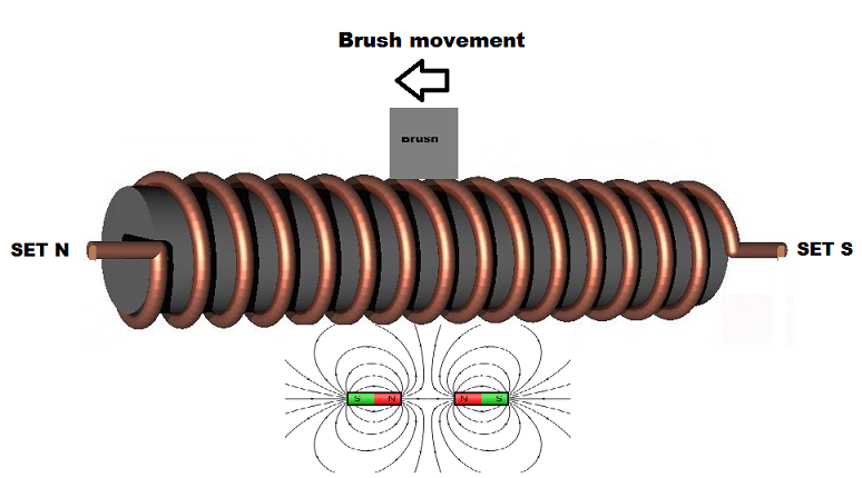 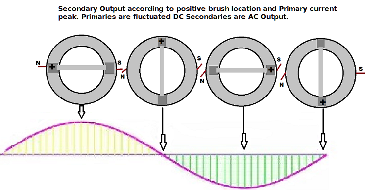 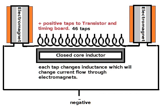 |
|
cheors
Junior Member
Posts: 33
|
Post by cheors on Sept 14, 2019 14:25:45 GMT -6
Your 46 taps coil can be seen as 45 small coils serial connected. I speak of mine with 13 taps and 12 coils.
|
|
|
|
Post by Marathonman on Sept 14, 2019 21:51:04 GMT -6
Sorry for the misunderstanding, i just never heard it described like that before. that is 46 loops with 46 taps with two end taps going to the electromagnets. are you sure just 12 loops are enough for a demo.?? not much inductance unless you have multiple loops per tap.??. just make sure it is on a closed core as an open ended core leaks flux to much.
MM
|
|
|
|
Post by Marathonman on Sept 15, 2019 17:08:30 GMT -6
I tested the program posted earlier and it is to slow for a 16 Mhz Arduino. it is the digital write and shiftout that is slowing it down so it has to be done either the way Cheors or with Spi working directly with ports then shifting using the << or >> shifts commands. i am working with the Arduino forum so i might get some where. maybe the new Tensy 4 with a clock at 600 Mhz would help but then again it is 3.3 volts so good luck finding a transistor that is fully on at that voltage that is worth a darn. i did fortunately find one that turns on at 3 volts and fully at 5 volts so i would use that to trigger a PNP on the high side.
MM
|
|
|
|
Post by Marathonman on Sept 16, 2019 16:49:58 GMT -6
Just so everyone knows 50 Hz in other countries is 50 cycles per second = 50 revolutions per second of mechanlcal brush rotation which is 1000 Milliseconds per second.
divide 1000 by 50 = 20 ms. so divide how ever many taps you have for electronic switching then double that + 2 for the ends on longer into 20 ms and that number is how long each channel have to be on to equal 50 Hz. in the US it will be 16.666 ms divided by your taps doubled + 2.
example say i have 50 taps so double that (up and back) plus two which will give the ends three times on longer. 20 divided by 102 = .196 ms or 196 us on each tap. the ends being on for three times longer is .588 ms or 588 us x 2 = 1.176 ms. the rest of them are 96 taps x .196 ms = 18.816 ms + 1.176 = 19.992 ms x 50 per revolution = 999.6 ms x 50 revolutions per minute = 49980 ms divided by 1000 = 49.980 Hz which is probably closer then your utilities.
i would also add that most shift registers put out in the low 30 to 70 milliamp range unless you have a logic level NPN to switch something higher amperage. i have been trying to find a logic level to switch at a higher current to no avail. i did find shift registers that output much higher milliamps and they are TPIC6C595 @ 100 ma continuous and TPIC6B595 @ 150 ma continuous with a peak @ 500 ma. both are well worth the 1.40 price tag. the outputs unfortunately are mixed with half on one side half on the other which will make for some fancy routing unlike the Nexperian 74HC595 that has all the output on one side except Q0 which makes for a clean routing.
Cheros;
i would like to see your version of port manipulation with overlap in action. it looks like one could have two bits on shifted side to side with the end delay longer.
MM
|
|
cheors
Junior Member
Posts: 33
|
Post by cheors on Sept 17, 2019 2:08:48 GMT -6
Here is my 13 bits test routine for 50Hz
/*
For 50Hz 20mS
48 steps ---> 20000us / 48 = 417
Add some time for PartG both ends :
T2 = T1 + 100, T3 = T1 + 200 -->> (100 + 100 + 200) * 2 = 800 uS
20000uS - 800 = 19200 / 48 steps = 400
PORTx need some time, so we choose :
T1 = 398, T2 = 498, T3 =598
*/
PORTD =0b00000011; // Bits 0 1
delayMicroseconds(T2); // add 100uS
PORTD =0b00000001; // Bit 0
delayMicroseconds(T3); // add 200uS
PORTD =0b00000011; // Bits 0 1
delayMicroseconds(T2); // add 100uS (400 uS total)
PORTD =0b0000010; // Bit 1
delayMicroseconds(T1);
PORTD =0b00000110; // 1 2
delayMicroseconds(T1);
PORTD =0b00000100; // 2
delayMicroseconds(T1);
PORTD =0b00001100; // 2 3
delayMicroseconds(T1);
PORTD =0b00001000; // 3
delayMicroseconds(T1);
PORTD =0b00011000; // 3 4
delayMicroseconds(T1);
PORTD =0b00010000;
delayMicroseconds(T1);
PORTD =0b00110000; // 4 5
delayMicroseconds(T1);
PORTD =0b00100000; // 5
delayMicroseconds(T1);
PORTD =0b01100000; // 5 6
delayMicroseconds(T1);
PORTD =0b01000000; // 6
delayMicroseconds(T1);
PORTD =0b11000000; // 6 7
delayMicroseconds(T1);
PORTD =0b10000000; // 7
delayMicroseconds(T1);
PORTB =0b00000001; // 7 8 (bit 8 = PORTB bit 0)
delayMicroseconds(T1);
PORTD =0b00000000; // 8
delayMicroseconds(T1);
PORTB =0b00000011; // 8 9
delayMicroseconds(T1);
PORTB =0b00000010; // 9
delayMicroseconds(T1);
PORTB =0b00000110; // 9 10
delayMicroseconds(T1);
PORTB =0b00000100; // 10
delayMicroseconds(T1);
PORTB =0b00001100; // 10 11
delayMicroseconds(T1);
PORTB =0b00001000; // 11
delayMicroseconds(T1);
PORTB =0b00011000; // 11 12
delayMicroseconds(T2); // add 100uS
PORTB =0b00010000; // 12
delayMicroseconds(T3); add 200uS
PORTB =0b00011000; // 11 12
delayMicroseconds(T2); // add 100uS, 400 uS total
PORTB =0b00001000; // 11
delayMicroseconds(T1);
PORTB =0b00001100; // 10 11
delayMicroseconds(T1);
PORTB =0b00000100; // 10
delayMicroseconds(T1);
PORTB =0b00000110; // 9 10
delayMicroseconds(T1);
PORTB =0b00000010; // 9
delayMicroseconds(T1);
PORTB =0b00000011; // 8 9
delayMicroseconds(T1);
PORTB =0b00000001; // 8
delayMicroseconds(T1);
PORTD =0b10000000;// 7 8
delayMicroseconds(T1);
PORTB =0b00000000; // 7
delayMicroseconds(T1);
PORTD =0b11000000; // 6 7
delayMicroseconds(T1);
PORTD =0b01000000; // 6
delayMicroseconds(T1); // part G middle point
PORTD =0b01100000; // 5 6
delayMicroseconds(T1);
PORTD =0b00100000; // 5
delayMicroseconds(T1);
PORTD =0b00110000; // 4 5
delayMicroseconds(T1);
PORTD =0b00010000; // 4
delayMicroseconds(T1);
PORTD =0b00011000; // 3 4
delayMicroseconds(T1);
PORTD =0b000001000; // 3
delayMicroseconds(T1);
PORTD =0b00001100; // 2 3
delayMicroseconds(T1);
PORTD =0b00000100; // 2
delayMicroseconds(T1);
PORTD =0b00000110; // 1 2
delayMicroseconds(T1);
PORTD =0b0000010; // 1
delayMicroseconds(T1);
|
|
|
|
Post by Marathonman on Sept 17, 2019 9:50:50 GMT -6
Here is a graphical representation to readers/followers what Cheros (Electronic Switching Part G) is trying to accomplish. the whole point is to mimic the brush rotation as close to reality as possible accounting for the ends on for a longer time and the channel overlap as the brush makes contact with two or more contacts at a time in a "Make Before Break" scenario to reduce sparking and have an uninterrupted flow of current through the electromagnets. I would have 0 on first with a delay then add 1 then another delay. 0 goes low and 2 goes high and so on, that way 0 is on by it's self as would be the rotating brush. the same with channel 12. the true skeptic would be to test it then meter with an oscilloscope. Marathonman 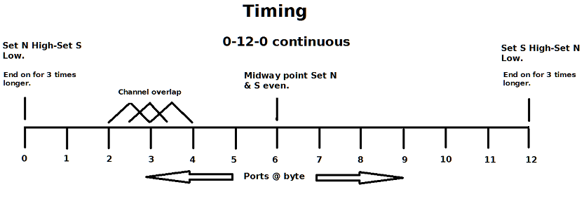 |
|
|
|
Post by Marathonman on Sept 17, 2019 23:10:43 GMT -6
The entire reason for having the ends on longer then the ones in the middle is from the inductive roll off to the secondary. with the rotating brush the ends are on ruffly three times longer then the ones in the middle and since the primary induction is dependent on constant changing current flow. the induction from the primaries to the secondaries at the ends being on longer will begin to loose induction from the hesitation. the current flow has not changed but the movement of the magnetic fields from side to side is delayed which will cause an inductive roll off of the secondary. by the time the roll off starts to curve downward the brush is rotating to the other contacts which will continue the downward slop as that primary is being reduced. this action causes the nice sine wave we need for our output.
if this did not take place and the primaries zipped right through the ends like the middle contacts then the secondary would output a saw tooth wave not a sine wave. this is why i have been harping on the ends on longer in the electronic switching to get this nice sine wave output plus the channel overlap for Make Before Break to eliminate current interruptions. shutting one channel off then turning on another will cause Cemf or Bemf if you prefer that will kill the device, everything has to be nice and flowing.
MM
|
|
|
|
Post by Marathonman on Sept 18, 2019 16:24:33 GMT -6
The code below represents the style of overlap i will be achieving with the coding. while not the exact code it is just a representation of the overlap to achieve Make Before Break scenario. i see only two ways of timing this beast and that is SPI or direct port manipulation. any other way is just to darn slow to operate at 50 or 60 Hz which is 2500 and 3600 RPM, 20 ms - 16.666 per revolution/ round trip respectively.
PORTD =0b00001100; // Bit 3,2
delayMicroseconds( ); //
PORTD =0b00000110; // Bit 2,1
delayMicroseconds( ); // End to zero
PORTD =0b00000011; // Bit 1,0 *
delayMicroseconds( ); //
PORTD =0b00000001; // Bits 0 *
*** end on for three times longer 1,0 /0/0,1
delayMicroseconds( ); //
PORTD =0b00000011; // Bit 0,1 *
delayMicroseconds( ); //
Zero to End
ORTD =0b00000110; // Bits 1,2
delayMicroseconds( ); //
PORTD =0b00001100; // Bit 2,3
This will be the exact operation for the other end at 12 except the ports change depending on the amount of ports used.
what i have also found is when shifting on the first time the count is right from bit 0 to 45 but coming back 45 to 0 you loose one pin and one delay. so when the program is running constantly you loose one pin and one delay each direction so what i had to do is increase the time of the delay from 177 us to 181 us which then added to the correct time of the round trip giving me a hair under 16.666 ms with two overlap at all times except the ends for which they are on for three times longer.
Timing solved.
MM
|
|
|
|
Post by Marathonman on Sept 19, 2019 9:50:11 GMT -6
Here is a copy of the shift register circuit that uses SPI instead of regular pins. SPI clock runs according to the clock divider relative to the system clock. On AVR based boards, the dividers available are 2, 4, 8, 16, 32, 64 or 128. The default setting is SPI_CLOCK_DIV4, which sets the SPI clock to one-quarter the frequency of the system clock, 4 Mhz for the boards at 16 MHz. so as you see SPI runs much, much faster then using regular delay, digital write and so on which has a lot of overhead. just like direct port manipulation that Cheros is using these two approaches being much faster that will correctly run the Arduino sketch at the intended frequency needed for proper part G electronic switching. Cheros's circuit will of course be a little different as he will have direct pin for pin ports used. i will be using a Byte DataArray () which uses binary data similar to Cheros except a slightly different approach. using << and >> to shift the bits left or right and using elapsedMicros = currentMicros - previousMicros; . what this does is update the clock every time the sketch loops which keeps the timing exact. i will post the sketch when completed but that will be a while yet as i need to complete the sketch and test it first so that will be a few weeks as i have other very pressing matters to attend to that requires all my attention. PS. Circuit can be extended for your build requirements adding more shift registers when needed, pin count to Arduino stays the same at 4. Regards, Marathonman 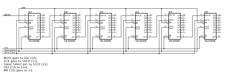 Attachments:
|
|
cheors
Junior Member
Posts: 33
|
Post by cheors on Sept 20, 2019 0:22:46 GMT -6
To avoid sparking it is better to alternate register commands : Switch on or off a bit pertaining to PORTx then the next one to PORTy: Example : ..... PORTD = 2; // Bits 1 8 delayMicroseconds(T1); PORTB = 0; // 1 delayMicroseconds(T1); PORTB = 2; // 1 9 delayMicroseconds(T1); PORTD = 0; // 9 delayMicroseconds(T1); PORTD = 4; // 2 9 delayMicroseconds(T1); PORTB = 0; // 2 delayMicroseconds(T1); PORTB = 4; // 2 10 delayMicroseconds(T1); PORTD = 0; // 10 delayMicroseconds(T1); PORTD = 8; // 3 10 delayMicroseconds(T1); PORTB = 0; // 3 .....
PartG wiring will be :
Current waveform :
|
|
|
|
Post by Marathonman on Sept 20, 2019 8:09:11 GMT -6
"is better to alternate register commands :" Please define better as oppose to not better.
have you physically tested this or is this just your opinion from simulation. real world testing will reveal all and i see no real change whether it is the same port pins or two different ports pins going high.. i will ask on the Arduino Forum whether it makes a difference or not to well seasoned veterans as i have learned to no fully trust simulations. another thing is what does none sparking have to do with the port pins. being solid state there will be no sparking at all i just use that phrase from the mechanical version to instill the importance of "Make Before Break". if any ports used are not overlapped current flow will be disrupted and BEMF will form in part G and the system is dead from that point on.
BEMf in the system is way different in form from a time varied release of potential into the system. the time varied release is a calculated release to gradually increase the overall voltage in the system to forward bias the rising side for which an increase in voltage there will be an increase in current flow. BEMF on the other hand will induce a vary large voltage spike into the system which will unbalance the system and it is dead from that point on and needs to be restarted.
part G's wiring will be the same irregardless of Arduino coding. there will be a finite amount of taps "IF" your inductances are right in the first place. if you actually took a working part G with the proper inductances from mechanical then switched it over to electronic it will still have the same inductances just a tap on each wire wrapped around the core just like a real rotating brush does with two contacts at a time through out the rotation except on the ends.
we will work together on this issue which will benefit the entire Figuera electronic community. anyone out there, members and non-members alike, please come forward if are a seasoned coder to join in on this good cause as the end result will only benefit humanity not rich bankers, Corporate or rotten greedy Governments.
regards,
MM
|
|


