|
|
Post by Marathonman on Sept 28, 2019 15:54:47 GMT -6
Dug out my Arduino Leonardo, dusted it off and programmed it today with the latest code. i didn't even have to change any pins so that was nice. after i test the program next week i will give a glimps of the sketch. i do not know if people use these plastic feet but i find them extremely helpful. when put into my Aquaponic system all i have to do is screw the feet down and i am good to go. that is what my Leonardo was for but i need it to run this program but that is nothing but a reflash. i actually have two digitalwriteFast in the program which was suggested my the Forum member. i changed the delay from micros() to millis() so i can see the code at work for adjustments. when in actual service it will be changed back to micros(). Arduino IDE 1.8.10. is out so i updated my IDE. if you use any Tensy's Paul S has not fully supported the new IDE as of yet with just a beta Tensy stool set. MM 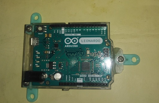 |
|
|
|
Post by Marathonman on Sept 29, 2019 9:00:30 GMT -6
Here is a quote from the member i am dealing with on Arduino forum.
"The reason that digitalWriteFast is not implemented on many other platforms is, I think, because it's advantages aren't so dramatic on those platforms. On AVR chips like Atmega328,2560,Uno,Leonardo direct port manipulation can be 10~15 times faster than digitalWrite(). But on esp8266,Tensy 3 - 4 for example, it's only about twice as fast, so why bother? I think this is because of the large number of Arduino pins that ATmega chips have compared to their port size, which is 8 bits, and the number of ports which don't have all 8 bits available because they are used for other things like crystal oscillator inputs. So translating an Arduino pin number to a port and pin number is complex. On other chips, it's much simpler, because their ports are 16 bits wide, for example."
so now it makes sense of why digitalWriteFast is only implemented on a small number of IC's. the speed advantage is minimal at best.
remember digitalWrite is very slow from the conversion to identify the actual pin, digitalWriteFast was changed at the macro level to deal with direct port manipulation which was advantageous to certain slow platforms.
most people now a days are hypnotized by Corporate world to think they always need the latest and greatest gismo but in this case a 5- 8 dollar 32U4 off of ebay will handle this switching job just fine in my case. as i have stated before "why add more complexity then needed."
other programs will need more pins obviously.
Regards,
MM
|
|
|
|
Post by Marathonman on Sept 30, 2019 17:07:49 GMT -6
Good news some of my parts came in today for the electronic switching. breadboard has an AC power plug built in with DC +5 and +15-15-volts to the board. still waiting for new slip ring. MM 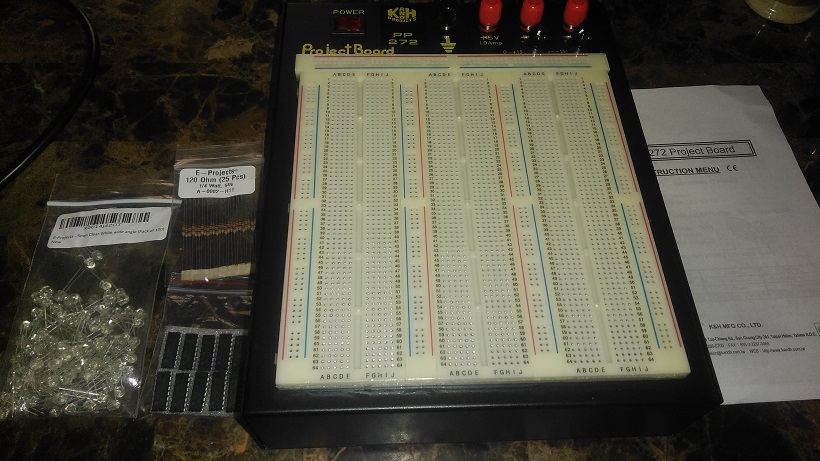 |
|
cheors
Junior Member

Posts: 33
|
Post by cheors on Oct 1, 2019 7:54:45 GMT -6
My complete assembler coding for a 13 bits PartG with fixed or variable frequency capability.
_  |
|
|
|
Post by Marathonman on Oct 1, 2019 8:32:04 GMT -6
That is so awesome Cheors, i can not wait to see it in action. it is breadboard time or what?  got to test. i simply love my new breadboard. it has built in power supply and is quite heavy being on a solid metal box that houses the power supply. i have most of the circuit layout done already, just waiting for some resistors and capacitors. can't seem to find my solid core wire though, search everywhere to no avail. Quote from Arduino forum; "SPI" is specialized hardware inside the ATmega chip which can shift out data one bit at a time with an accompanying clock signal. The SPI circuit can do this much quicker than a piece of code could, and does it independently of the CPU, which can running other code while the data is being sent." what this means is i can add to the code i already have to install current, voltage and frequency sensors to monitor in real time then update a display or even send to remote monitoring station to alert the user of any such changes in operation or imbalances. man this project is turning out to be an awesome adventure. i will finish what i have, fine tune it then post what i have, then at a later date i can add the sensor and or remote monitoring as an update. the good thing about using SPI is all i have to do is designate an SS pin (Leonardo) for pin 12 on the shift register with the other SPI pins varying per your 32U4 board. the code takes care of the rest as those other pins are already included with the use of SPI. using the (Tensy 2.0) it has a designated SS pin B0, SCK pin B1 and Mosi pin B2. everyone knows the 32U4 can be had for a really cheap price pretty much anywhere. MM |
|
cheors
Junior Member
Posts: 33
|
Post by cheors on Oct 1, 2019 9:59:46 GMT -6
|
|
|
|
Post by Marathonman on Oct 1, 2019 13:42:49 GMT -6
Wow, i love those May West scope shots. i am in love. very nice indeed.
question ? how far are you reducing your electromagnets? the reason i am asking is induction will fail taken below half way. the optimum is to just reduce to remove the reducing electromagnet from the secondary core then back to full potential. of course this depends on the ratio of primary to secondary, core material, winding's ect.... also are you overlapping your channels.??
sorry i did not get a chance to review your code yet.
MM
|
|
|
|
Post by Marathonman on Oct 2, 2019 19:40:27 GMT -6
One good thing is the reaction of the inductor will not be stair stepped like that though as induction does not react like that. it will be much more gradual then the simulations are.
i am so mad today as i can not find my rolls of solid core wire i had for the breadboard circuit. i was so desperate i cut up sata cables for the wire and then even ran out of them. how pitiful.
MM
|
|
|
|
Post by Marathonman on Oct 6, 2019 9:28:23 GMT -6
Was working on electronic circuit yesterday. i pulled out oscilloscope to test the frequency on the Arduino with the program loaded but it seems my ex roommates strike again. my oscilloscope is broken as it seems the inputs are fried with no reaction what so ever. i do not know if it was dropped on the floor or something dropped on it but knowing those two sorry people they did it on purpose.
so now i am stuck with no way to test a single thing on this project what so ever except for LED's to tell me it is working. talk about a depressing week end.
MM
|
|
|
|
Post by Marathonman on Oct 8, 2019 16:44:41 GMT -6
I am sorry for the delay on the Arduino sketch as i have been extremely busy the last few days trying to straighten out the mess i am in from my past heath fail. sill working on the sketch trying to add some timing features so it resembles the brush rotation exactly. proper mirosecond delays have to be just right as is the SPI shift of bytes. plus i have run out of connecting wire fore which i need 20 to 22 awg solid for my breadboard. one thing i did finish is my transistor board as you see below. i was able to squeeze this in a two layer board which cuts down on cost. all the power and ground traces are on the outside and the digital traces are on the inside. i even kept the digital ground return away from the digital input lines and the power traces that is why i split them up in two on each side of the board. i know i have made boards before but this is the real deal that will be used in my electronic switching when i finish my mechanical part G. it consist of a 2.5 volt RDS on logic level enhanced n Channel Mosfet which turns on a enhanced p channel Mosfet using a voltage divider on the P channel gate, both are 200 volt. it also has a resistor on the digital line with the addition of a timing overlap if needed just in case, there might be other additions to the circuit when i test it. of course i will test it before i have it made but i just wanted to give you a heads up as to where i am right now in my design. regards, MM 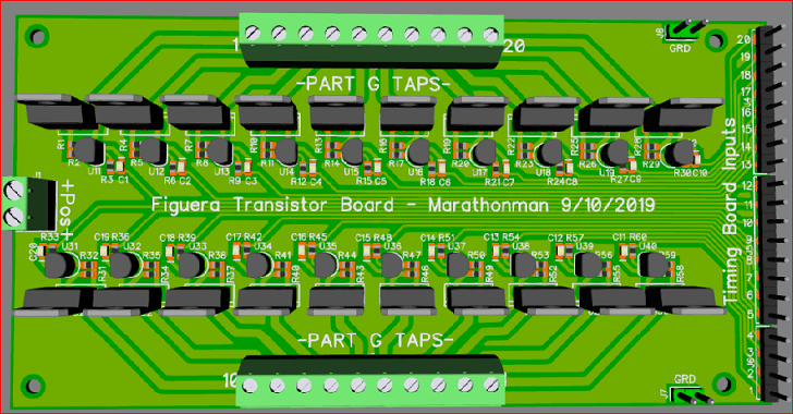 |
|
peter
New Member

Posts: 24
|
Post by peter on Oct 9, 2019 1:05:57 GMT -6
Very nice PCB , be shure to have a couple of these made. I would really like to buy one  |
|
|
|
Post by Marathonman on Oct 9, 2019 8:28:20 GMT -6
Thank you Peter for the vote of confidence. i change the above as i labeled the digital as on the outside when they are obviously on the inside. i also found heat sink on ebay to fit in the space where the transistors are. they are only on for for 177 us with the ends on for 3 x 177us so it is really not enough time to even think about getting hot so the heat sink is just for looks and precaution.
traces are only 1oz copper but are wide enough to handle a peak of 3.8 amp max but at 100 volt there needs to be a certain amount of trace gap so the size of the trace is limited especially at the transistor legs. the good thing about this is 20 transistor circuits per board so with my case i only need three with the last one having only 6 circuits soldered to the board. since the boards are relatively small at 3.1 x 6.1 inches it fits in the palm of my hand.
the timing board i have designed has provisions for a Tensy 2.0 or even an Arduino pro mini attached directly to the board with 12 pins on either side. both are 32U4 Atmel chips so they are relatively inexpensive with the use of SPI for speed @ 8 mhz top speed which is way more then what is needed for the function of attaining or to mimic 3600 rpm brush rotation which was calculated in the range of 330 or so khz.
what made it easy with the Tensy 2.0 is it has dedicated SS, SCK and MISO pins which is B0, B1 and B2 on the left side of the board with ground as the first pin then SS, SCK and MISO respectively. but that does not mean the program is limited to just that board as that can be changed to other pin assignments. also the good thing about the timing board is it is under 100 mm so the boards at PCBWAY are 10 for 5 bucks which can not be matched. hell shipping it to the US cost more then the boards themselves.
even though i am replicating the mechanical right now i will at a later date purchase another core to switch with electronics so that is why i am aiding in the advancement as i have dead time with the mechanical right now as i am in need of additional parts (funds). i will of course be switching every loop around the core instead of grouping like everyone else as the purist in me tells me to mimic the brush rotation exactly so that is my entire goal of my design of the boards. i also have not mentioned the addition of the secondary feed back into part G which will be in future post that will explain reasons of it's implementation.
PS. i use DipTrace for my PCB design which has 500 pin max. the free version is 300 pins. since i do not game any longer i have my 580 GTX maxed out for visuals so the PCB's in 3D look rather good.
Regards,
Marathonman
|
|
|
|
Post by Admin on Oct 18, 2019 5:11:57 GMT -6
I would like to add that one of our members Cheors has requested to become a builder. Absolutely and welcome to the builders community. i hope what i have posted have increased your knowledge of the Figuera device to guide you in your new journey.
welcome Cheors.
Regards,
Marathonman
|
|
|
|
Post by creasysee on Oct 20, 2019 5:56:44 GMT -6
Cheors, welcome on board!
We believe that we will succeed!
Regards,
creasysee
|
|
cheors
Junior Member
Posts: 33
|
Post by cheors on Oct 20, 2019 13:32:33 GMT -6
Many thanks MM and creasysee. I'm going to build something soon.
|
|


 got to test.


