|
|
Post by Marathonman on Oct 20, 2019 17:54:51 GMT -6
Isn't that a little vague chief.?
Here is the sketch for the electronic switching i am working on. while not complete or thoroughly tested as i might change the outputs. all in all it is coming along very well.
[code]
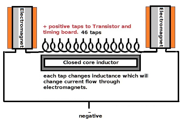
// This sketch controls multiple 74HC595 shift registers in cascade to electronically control Figuera's active inductor
// controller by switching on taps located on part G connected to transistors in a "Make Before Break" scenario. by changing
// tap locations continuously changes inductance which controls current flow of the primaries.
// this sketch utilizes timing overlap to eliminate back Bemf or Cemf that would ocurr with single on off tap. it mimics
// the brush rotation of a mechanical rotating brush thus creates a continuous increase/decrease current through the primaries.
// this sketch is distributed freely but if you use this program then post build on line give credit where credit is
// due and not claim as your own design.
// to adapt to your build change pin numbers, delay time.
// developed for the electronic Figuera community by (DL)aka Marathonman with all technical help of PaulRB on Arduiono.cc Forum.
// Mosi to DS in pin 14 on 74HC595
// SCk to Seial Clock SHCk Shift Clock pin 11 on 74HC595
// SS or CS output to STCK latch pin 12 on 74HC595
#include <digitalWriteFast.h>
#include <SPI.h>
unsigned long long int registerBuffer = 0b11;
byte shiftPos = 0;
bool shiftingLeft = true;
unsigned long int lastUpdate;
unsigned long updatePeriod = 177UL;
const byte latchPin = 10;
void setup() {
Serial.begin(115200);
SPI.begin();
SPI.beginTransaction(SPISettings(10000000, MSBFIRST, SPI_MODE0));
pinModeFast(latchPin, OUTPUT);
}
void loop() {
if (millis() - lastUpdate > updatePeriod) { //Is it time to update the registers?
lastUpdate = millis();
//Shift the register left or right
if (shiftingLeft) {
registerBuffer <<= 1; //Shift 1 place to left
if (++shiftPos == 47) shiftingLeft = false; //Time to switch direction?
}
else {
registerBuffer >>= 1; //Shift 1 place to right
if (--shiftPos == 0) shiftingLeft = true; //Time to switch direction?
}
unsigned long long int temp = registerBuffer; //Take a copy of the buffer
SPI.transfer(&temp, 6); //Send the buffer to the registers
digitalWriteFast(latchPin, HIGH); //Latch the updated values into the register's output pins
digitalWriteFast(latchPin, LOW);
}
}
[/code]
EDIT;
The regular digitalWrite() in Arduino Uno, Leonardo ect.. core (16MHz) takes about 6280nS each while digitalWriteFast() port manipulation takes 125nS with Paul's new implementation of macros. so you see two digitalWriteFast at 125 ns is still plenty fast enough for 16.666 ms per brush rotation program with room to spare.
EDIT;
All SPI pins if available will not have to be declared as we are dealing with hardware level not software. if the SS pin is not available like tied to RX then any pin can be used for SS pin then needs to be declared in setup then controlled their after. all SPI is automatic, if multiple SPI's are available then SPI0. SPI1, SPI2 ect needs to be declared in sketch from beginning.
MM
|
|
cheors
Junior Member

Posts: 33
|
Post by cheors on Oct 21, 2019 3:51:18 GMT -6
My Arduino Nano new version :
 I changed and now use PORTB , PORTD , PORTC (6 + 6 + 1 bits)
With the A7 switch we can choose a fix frequency (50Hz) for me, or adjust it with the potentiometer (A6 analog input) up to 16KHz
My fully tested assember code :
 _ |
|
|
|
Post by Marathonman on Oct 21, 2019 8:49:39 GMT -6
I am curious as to the identification of the 7 chips in the middle.
MM
|
|
cheors
Junior Member
Posts: 33
|
Post by cheors on Oct 21, 2019 14:54:35 GMT -6
TC4424 double mosfet driver
|
|
|
|
Post by Marathonman on Oct 24, 2019 8:47:16 GMT -6
The reason i chose to go the route with N & P channels is the low power it take to turn them on. all i am trying to do is minimize the draw on the feed back or the draw presented to the device as a whole. if you or anyone else for that matter plan on using LED's i would suggest using low power ones like the 2 ma kind. i personally do not see the need for them as it is functioning at 50 or 60 hz there is no visual light channel separation so i do not want to waste the potential on flashy needless things.
logic level N channel transistors fit the bill for me just fine as the simple the better scenario comes to mind.
i have solved the difference in timing of having the ends on for three times longer with a simple solution. since i have two extra channels on the board i will use them for the ends as in having two channels connected to both ends. this will alleviate the addition of adding an extra timing for the ends adding to the complexity of the software coding.
my timing will be as 3/2, 2/1, 1/0, 0/0, 0/1, 1/2, 2/3 and the other end will be 45/46, 46/47, 47/48, 48/48, 48/47, 47/46, 46/45 ect. as you can see the extra channel now allows me to stay with one set timing delay not two which will add to much complexity to the coding.
of course the transistor boards stays the same as only the timing board was changed.
i am curious Cheors would it not be simple just to add a two sided slid switch so to set the frequency to 50 or 60 hz which is what all countries deal with.? what i mean is what material can you get that is cost effective that goes to 16 khz that is useful to the average person powering their home. none that i can think of.
Regards,
MM
|
|
|
|
Post by Marathonman on Oct 25, 2019 10:22:46 GMT -6
I personally am glad you Cheors and Creasysee are here and developing other systems as in the long run people will have multiple choices to choose from. i have always been interested and fascinated in how diversified people can be in their personal choices. interpretations can vary so widely among people which can be a good thing at times and a bad thing at others.
i have chosen the literal path to take from my previous military experience. it is quite funny that when observing and accident you will get 10 different stories yet with the military the odds of them all being the same and correct or closer to 100 %. maybe that is why previous enlisted people get along so well i imagine.
anyways, happy building and testing.
MM
|
|
cheors
Junior Member
Posts: 33
|
Post by cheors on Oct 25, 2019 13:47:06 GMT -6
i am curious Cheors would it not be simple just to add a two sided slid switch so to set the frequency to 50 or 60 hz which is what all countries deal with.? what i mean is what material can you get that is cost effective that goes to 16 khz that is useful to the average person powering their home. none that i can think of. Regards, MM At the moment, my goal is to see what happens with an variable frequency (is there some form of resonance ?) ,not to choose between 50 and 60Hz
The schematic
As you can see i use TC4424 drivers and channel N mosfets (IRLZ44N) to connect taps To ground.
PartG and primaries will always be connect to the positive side of a low voltage high current source (+2v for example). It is the ground (negative wire) that is is then switched on and off from PartG,
not the positive wire of the power supply. I think it's more simple and very efficient.
I have a SIL40C module converter (12v to 0.9 to 5V 40A adjustable power supply) for that.
|
|
|
|
Post by Marathonman on Oct 25, 2019 15:08:09 GMT -6
this is not how the mechanical part G operates as does the primaries as they are connected to the negative side. i think you are testing with to low of voltage and also Figuera device is not a high amperage device. also how will you account for the secondary feedback into part G knowing part G opposing fields acts as a rectifier to the secondary feedback and limits it's current and the starting supply.  ? test will reveal all. MM |
|
|
|
Post by Marathonman on Oct 27, 2019 22:09:40 GMT -6
I am most certainly not trying to detour you in any way shape or form. i am simply trying to raise your awareness of other actions taking place in the device that you might have overlooked some how.
My approach was to take all the actions/functions of the mechanical part G written down on paper, then fitting a circuit to execute that outline of events as exactly as i can possible do.
i will tomorrow draw up my approach to adding the secondary feedback into part G electronically that will exactly mimic the brush rotation while still maintaining the rectification properties.
Regards,
Marathonman
|
|
|
|
Post by Marathonman on Oct 29, 2019 22:02:31 GMT -6
To the best of my knowledge of the Figuera part G knowing the secondary is fed back into part G to replace loses and to give rise to amplification to the rising primaries. i suggest the electronic switching is to mimic the rotation of the brush exactly as possible. below in my implementation to the best of my ability does just that. as you look at the top one the negative is the feedback from the secondary through a commutator as is the positive combined with the power supply starting positive. as they rotate the secondary will either be increasing in potential or decreasing in potential always opposite of the positive brush. when the secondary is at peak it will be at the input of the low side of part G adding to the other released potentials to offset the rising side potential drop from storing into the magnetic fields giving rise to amplification. this way it will travel through part G to be regulated by part G's twin opposing magnetic fields. it travels through part G then returns to the other side of the secondary as all electricity and coils do. once stored and released from the magnetic field it is then part of the exciting system thus circulated through out. the second pic is the electronic part G taps that the transistors connect to. if you notice the secondary feedback is 180 degrees from the positive side just like the brush. it to like the mechanical version will release it's secondary potential at peak when it is opposite of the positive input when at set N or S. this setup mimics the rotating brush to the letter as long as the overlap of the channels take place with the ends on for three to four times longer. the tap and transistor count will be exactly as the positive side just starting from the opposite end traveling the opposite direction. to the best of my knowledge this will mimic the brush movement exactly. if you are worried that the two will be direct short when even in the middle, please remember that the secondary feedback will also be at zero as per the previous graph i have already posted on secondary and brush position which i reposted below. the addition of Figuera adding an inductive motor to the system keeps this secondary field aligned and timing in correct position. the black dots which are kind of hard to see are the location of taps coming off of part G to the transistors. one is coming in the other is going out so plan accordingly with your transistors orientation to part G. the switching of the negative side can be tied to the positive side switching just 180 from each other as so to start and end opposite from each other. i hope this makes as much sense to you as it does to me. PS. i know the second pic has more contact as this is just for understanding to get the point across. in reality they will have the same amount of winding contacts and inductance to get the sweeping action of the primaries only- no more- no less. Regards, Marathonman 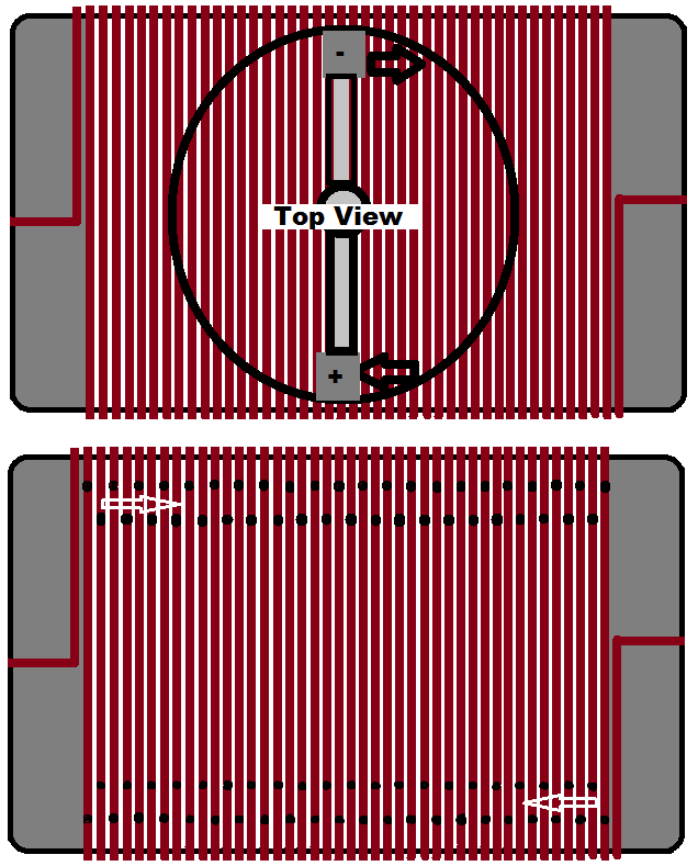 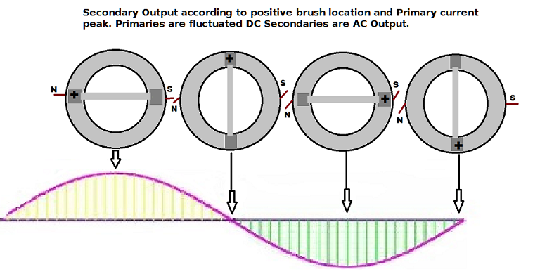 |
|
|
|
Post by Marathonman on Oct 31, 2019 9:44:01 GMT -6
With Part G set up in the fashion of the last post one will be able to test the device with just the positive taps and negative leads to primaries to check on the balances of the primaries. after the primaries have been adjusted for proper balances and sweep, the addition of the secondary feedback can then take place by adding the taps to the other side of part G's core. you can then change the wiring to loop the device to self sustain. the addition of n channel Mosfets to the secondary feedback will fit this bill that can then be attached to the timing board opposite to the positive switching direction.
this addition of secondary feedback can be on a separate board with interconnects or even on the same board but with the added expense of a larger board.
with this type of switching it will mimic the mechanical brush movement and the secondary feedback exactly being 180 degrees opposite from each other.
Regards,
Marathonman
|
|
cheors
Junior Member
Posts: 33
|
Post by cheors on Oct 31, 2019 11:35:36 GMT -6
this is not how the mechanical part G operates as does the primaries as they are connected to the negative side. i think you are testing with to low of voltage and also Figuera device is not a high amperage device. also how will you account for the secondary feedback into part G knowing part G opposing fields acts as a rectifier to the secondary feedback and limits it's current and the starting supply. ? test will reveal all. MM I don't see the problem. I have the same wiring as you drew below, except the power supply is inverted: primaries electomagnets go to + voltage and taps, transistors go to ground. The functionality should be identical (of course currents run the other way) I only have 13 taps (3 loops between them). For test purpose, i intend to limit the current with a low voltage power supply.
|
|
|
|
Post by Marathonman on Nov 1, 2019 10:14:55 GMT -6
Well i have no problem with you failing to realize the mistake because it is not my device, money or time. i would suggest you analyze your schematic going though the steps to identify possible problems.
good luck with your design, i wish you all the luck.
a word of advice from me from years ago to a replicator that ended up failing miserably with the so called "improved design"
"why do humans attempt improve a device before completely understanding the working parameters of the first. without replicating the original design with complete understanding it will literally be impossible to alter the design and expect it to actually work."
years later the person in question, after years of screaming i was wrong and he was right, admitted to me that he failed miserably and that i was right all along and that part G worked as i described.
for this very reason is why i, with the electronic version, will attempt to follow the mechanical as close to the original as i possibly can to minimize the substantial increase in failure from each deviation however so slight they are.
again good luck.
Regards,
Marathonman
|
|
|
|
Post by Admin on Nov 1, 2019 11:44:46 GMT -6
Member EmilP will be joining the builders group and heading up the 1932 Coutier device build. we have been exchanging information for about a year now on this device so Emil is well aware of all parameters involved.
good luck Emil and welcome to the builders group.
together all builder will make a difference in this screwed up world we call home.
Regards,
Marathonman
|
|
|
|
Post by Marathonman on Nov 2, 2019 18:01:31 GMT -6
I will study your circuit again just to make sure it isn't I who is making the mistake.
Regards,
Marathonman
|
|


 ?
?