|
|
Post by Marathonman on Jan 4, 2021 13:20:40 GMT -6
This circuit is for all you DIYers that build your own packs. this circuit is a spot welder that has more balls then almost any other spot welder on the internet. I myself am building one because of the packs i am building for a scooter for the kids. hopefully when i am done with the Figuera device i will never need a battery again.  Regards, Marathonman |
|
|
|
Post by Marathonman on Apr 28, 2021 13:50:46 GMT -6
I will be posting other things in this thread besides what i have here now. i have a hay chopper i built for 400 bucks which retails for 3,000 bucks. i am building a four wheel two seat car and also some custom three way speakers out of used pipe material and plumbing parts.
Stay tuned for the projects that are posted very soon.
Regards,
Marathonman
|
|
|
|
Post by Marathonman on May 2, 2021 17:15:22 GMT -6
I also dwelled into the realm of speaker building. i have always wanted to build a cheap set of speakers and see what type of creativity i can come up with. below is my almost finished creation. i will of course be adding a large sub to this system which will be great for my new 4K Tv i have hooked to my computer. these speakers were entirely made up of plumbing parts and wood connectors/braces. the three way crossover is hidden in the back of the tube and with threaded hollow lamp connectors connecting the pieces together. i am not finished but it will be painted gloss black and clear coated with white or gray black grill cloth. Regards, Marathonman |
|
|
|
Post by Marathonman on May 2, 2021 17:18:30 GMT -6
Here are the rest of the pics. the midrange speakers have not come in yet so it is a waiting game now but they still sound good and look crazy. Regards, Marathonman |
|
|
|
Post by Marathonman on May 2, 2021 17:35:25 GMT -6
I needed a way to chop some hay for the compost bin and as a cover for the top soil from drying out. my problem was everyone wanted major bucks for a hay chopper, like 3,000 buck. screw that i built my own hay chopper for 400 bucks and the pics are below. this thing works unbelievably good and saved a ton of money. the heavy duty used drum was 10 bucks, the blades are inverted high temper high flow John Deer, 50 bucks, the motor was 128 bucks off of ebay. the 1 inch shaft and pillow blocks are from McMasters, 120 bucks, and well as the pullies. add some odd and end nuts and bolts with a sprinkle of a welding rod and Viola, i have a hay chopper that saved me 2,600 buck that will last 10 times longer. as you can see i hate corporate crap and tend to build it myself. PS. blade spin at 2700 RPM and eat that ass up like no tomorrow. PS will post later the electric four wheel bicycle car i am building sitting on three blade 29 inch rims. Regards, Marathonman |
|
|
|
Post by Marathonman on Dec 9, 2021 17:06:42 GMT -6
I just installed some LED attic lights with the whole ordeal working just great. I purchased a 120/5 volt wall wart taking it apart then soldered longer wires to tap into the AC line then hot glued it inside the metal box. i then ran the LED lights in parallel to the small outlet box which is metal. i used the cover of the box as a heat sink mounting the Zero crossing relay directly to it. the 375 lb attic latter i installed has a small block of wood in the upper corner for which i used to mount an Automotive pin switch. the 5 volt power supply has a long enough cord to reach the pin switch so i drilled a small hole through the frame then wired it all up.
now every time the attic latter is pulled down the four 100 watt equivalent lights come on lighting the whole attic with very bright light. i really did not have to mount the relay on the metal front plate as i am only using 450 miliamp of current through the relay at 120 volts ie.. 54 watts. the attic was plywooded by me for storage and i could not be happier with this system of lighting. the solid heater ducts were removed in the center and replace with flex duct up overhead out of the way.
the whole system is inside the little metal box.
Regards, Marathonman
|
|
|
|
Post by Marathonman on Dec 9, 2021 17:09:56 GMT -6
Here is the circuit, very simple yet effective. the relay has zero crossing circuit and a built in current limiting resistor on the DC input side so no external resistor required. it draws only like 16 miliamp on the 5 volt side with the 120 volt triac leaking only 6 miliamp when off.
All parts were purchased from All Electronics, ebay and Home Depot for the wire and LED's. whole project was maybe 75 bucks. Regards, Marathonman
|
|
|
|
Post by Marathonman on Feb 4, 2022 21:25:44 GMT -6
Working on a voice activation circuits. 1. is Arduino PWM using the V3 voice activation module which changes the PWM of an output to a opto Triac that triggers a Diac then a 10 amp Triac. 2.using the V3 module alone which has 7 outputs fore which I will be using 5 in the following manor. 100% 75% 50% 25% Off each output is connected to opto triacs to resistor that have different resistance to the Diac then Triac. my test boards are as follows. the first one is PWM using an Arduino tied serially to the V3 Voice module. the second is using the V3 alone attached to the switching board. the third is the circuit i am using for test bed. the whole purpose for this is to switch on lights with Voice activation not tied to the lousy internet that can eve drop on you.    Regards, Marathonman |
|
|
|
Post by Marathonman on Feb 6, 2022 12:08:10 GMT -6
In the above post the circuit can be altered for motors which need to add an inductor on the AC side as well as a snubber circuit for the Triac for transients and RF reduction. this original circuit was from Swagatam @ www.homemade-circuits.com which i correspond with him quite frequently. after i am done with the PWM coding and testing of the circuit Swagatam is going to do a complete full page writeup on the Arduino PWM voice control circuit as well as Arduino CC posting. Regards, Marathonman |
|
|
|
Post by Marathonman on Feb 12, 2022 22:21:36 GMT -6
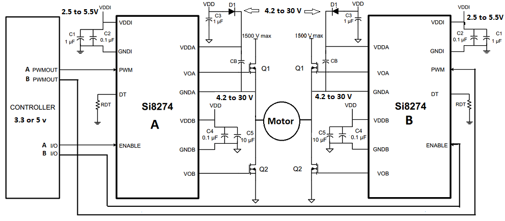
Here is a project a friend and I are working on so he can build solar trackers on his property. the problem is the ones on the market are either to low power or crazy ass expensive. i am designing the PCB for him. it is a duel H bridge solar tracker to control two motors ie N/S and E/W. the controllers are the IS8274 isolated half bridge driver IC from Skyworks. they use one PWM signal for each half bridge so two for each H bridge with a total of four PWM signals to the MCU (Teensy 4.1). they also have an en to enable or disable the bridges, two for each H bridge great for sleep mode at night. The tracker is not LDR controlled. it uses declination of the sun in radians then converted into an Arduino useable data downloaded from a guy on the internet. it will be modified for our use. the use of this instead of LDR's because one of his trackers were pointing at a bright cloud and the other to the sun. so to alleviate this problem he came up with this program free to download. i will post link later for everyone. The board is 12 or 24 volt capable with no jumpers to fool with just plug and play because all associated caps are set at 50 volts. also the 5 volt controller side of the chip is 2.5 to 5.5 volt capable so basically any MCU can be used and attached to this voltage supply and control the IC. the input of the 5 volt power supply also has 50 volt caps and can handle 30 volt input so no need for jumper. this is good for LiFePo4 batteries that generally get charger to 28 volts for 24 volt system. the input side of the board has smoothing caps but really not necessary just precautionary as batteries generally don't have voltage spikes like ac does. the controller high side input has an absolute maximum of 36 volts so it can quite easily handle 12 or 24 or 28 volt for that matter of the LiFePo4's. I will design it with an on board Teensy 4.1 for external remote communication with an android app to monitor system stats. the H bridge it self can actually handle 1500 volts running through the transistors but hey who in hell needs that much voltage. the actual board has the transistor H bridges lined up in a straight line so i can use heat sinks to form a tunnel with low power push pull fans just in case of summer heat dissipation even though the H bridges will not be on for that long. the longest time it will be on is when the east parking commences returning from west to east to align with the morning sun. it then goes to sleep until morning. this is an amazing project and i am glad i am able to help a fellow human being irregardless if he is my friend or not. Below is the circuit i am working with and of course when it is all said and done it will be posted here for free download along with programming. the circuit only shows one H bridge but the board has two with an additional four lines to the MCU. Oh, I almost forgot. the board is 12/24 volts and 20/10 amp capable respectively. BOOYA!  Regards, Marathonman |
|
|
|
Post by Marathonman on Feb 13, 2022 21:24:57 GMT -6
|
|
|
|
Post by Marathonman on Feb 15, 2022 0:06:06 GMT -6
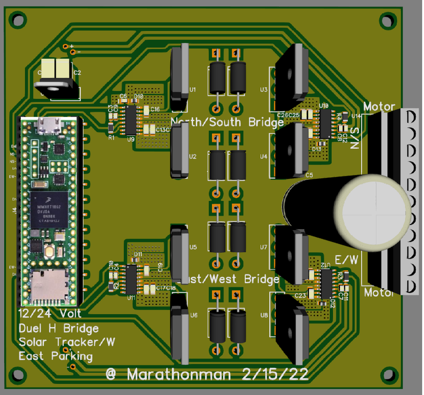
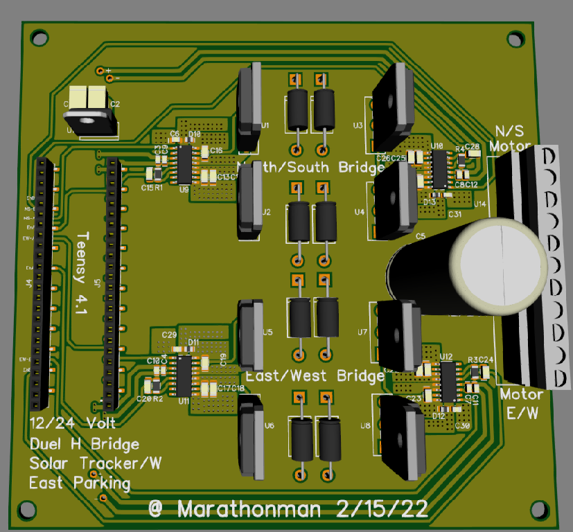
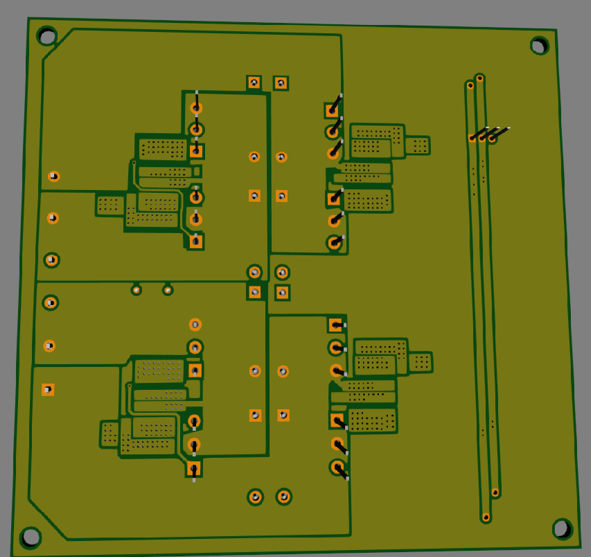
Here is the duel voltage, duel H bridge solar tracker with east parking, work in progress. i was going to use full bridge IC's but i can get closer to the H with these Skyworks IS8274 PWM isolate drivers. as i said it has separate power supplied for both sides of the IC chip. since all IC' on the board can handle 30 volts there is no need for jumpers at all. this will be a plug and play 12 or 24 volt system that can handle regular batteries or LiFePo4 cell system of 28-29 volts. the Teensy and the digital side of the driver is powered by a 5 volt supply that can handle 30 volt input. plus the digital input of the drivers can handle 3.3 or 5 volt Arduino's or MCU's. like i said the H bridges are lined up for heatsink's on both rows of Transistors to form a tunnel for low power duel fan forced air cooling. it is my attempt to surpass most everything on the market in terms of power and usability. also what is not showing is the wifi and or blue tooth modules which connect to the Teensy which can then be monitored with an Android app for constant monitoring and updates on system. all in all i am so far pleased with my results and can not wait to see this baby rock. the missing traces of the H bridge is on the bottom layer which will have copper pores to give this board a 20 amp capability at 12 volts or 10 amp at 24 volts. I hope you like it because when i am done it will be open source all the way. Updated pic of board, traces were all routed to Teensy Power, Grd and PWM pins that are least used by other important outputs...ie Can, I2C, Serial, SPI, Prop ect... so I can add wireless, sensors, GPS. APP Communication ect.
More updated pics of front and back. look at those massive trace copper pore on back side third pic. seems no DIY"er has traces this big.   The IGBT's i had from years ago came in really handy for this board project. they can quite easily handle 240 watts at 12 or 24 volt. IGBT at 650 volt 40 amp 405 watt beast. Regards, Marathonman |
|
|
|
Post by Marathonman on Feb 15, 2022 17:36:29 GMT -6
I am having a real hard time with Diptrace now a days. it seems they took a bunch of simple quick and easy parts out and now i am having a lot of difficulty finding pats in the program. even using the filter on board it is talking three times longer to design a board then when i used 2.4. the latest 4.1 to me is pure junk and major difficult to find right parts. not only that they are really lazy in the 3D department. some parts are just plain black blocks that look like a 10 year old designed them. even though they partnered with Snap EDA for 3D parts and such i can still see the laziness in their approach. they are making DipTrace overly complicated and the boards copper pores flash like crazy when you drag your mouse over the board. even the manual trace tool is now so quirky.
I also have involentary trace size change often from .025 to .024 by it's self and as you can see above the board mount holes moved on their own. how do you think i feel i when designing a board and it has a mind of it own. also the later versions are not backward compatible what so ever and if you try open with an older version the board is trashed with many mistakes and thing moving on their own. not only that but the 3D in 2.4 is completely trashed and useless freezing up when installing an newer version. so it seems they are deliberately trashing 2.4 to get you to buy the newer version..... how pathetic!
so in the end i can no longer recommend DipTrace to anyone unless they get off their dead asses and fix these glaring mistakes and stop overly complicating a use to be good thing.
Edit;
Downloaded 4.2 and i see a improvement but still glichy. it does render 3D well though.
Regards,
Marathonman
|
|
|
|
Post by Marathonman on Feb 17, 2022 11:43:51 GMT -6
I am even contemplating throwing a 7 to 10 inch touch display capability in the mix to ease the process of setting the whole system up. this of course if i get someone involved with the programing as that is way beyond my means. if there is a software guy out there to share their expertise i would be willing to furnish a complete board to you free of charge for testing and software tweaking. either that or i will source s local software person. This of course in conjunction with the wireless connection to the Android App which will take more time if i am to have it able to change system setting instead of just monitoring. as you may see i am a hardware guy not a software guy unfortunately for me. of course i could always use a portable tablet with USB C connection for programming then jus use the App to monitor which would probably be the best bet. all in all quite a fun project. edit; The pic below is the push pull fan system i am incorporating on the board. the black area is the heat sink, the grey at the top is to enclose it to form a tunnel and the blue is the low power push pull fans.  Regards, Marathonman |
|
|
|
Post by Marathonman on Feb 19, 2022 8:38:41 GMT -6
Basically the board is done. so now i will go through it with a fine tooth comb making sure everything is straightened up. I thought about on board sensors but they will be just plug and play to be the easiest on the teensy. all usable pins will have headers soldered on them facing up so no worries there. Lke i said the Gerber will be posted here as well as the software when i am finished. software is still a month or so out though. lots of testing to be done.
Regards,
Marathonman
|
|