|
|
Post by Marathonman on May 9, 2020 11:53:56 GMT -6
VL = induced voltage in volts
N = number of turns in the coil
dφ/dt = rate of change of magnetic flux in webers / second.
This according to main stream science takes place when there is a change in current flow that changes the magnetic flux and is the only thing that is taught in schools and colleges around the world. This is not the whole picture because inductance and current change are interchangeable as in either one can control the other. If you have say two amps flowing through a changing loop count dφ is changed which is the amount of flux created within the circuit per the amount of current flow. What this does is change the magnetic flux to current ratio which in turn reduces the current flow through the circuit. As long as the loop count is constantly changing within the time constant of the circuit you will have a constant change in current flow from high to low which is exactly what Clemente Figuera did with his controller. And this my friends is in exact accordance with Faraday's laws of induction that states ANY change in flux creates EMF no mater how it is changed.
Regards,
Marathonman
|
|
|
|
Post by Marathonman on Jun 8, 2020 17:13:59 GMT -6
DC you look like AC, Your Impeded!
As the brush moves around the contact points of the inductor controller, what is happening is the coil count on either side of the brush is changing, either increasing or decreasing . The magnetic field associated with that side of the inductor controller is also increasing or decreasing, so everyone should know by now that the coils magnetic field "impedes" the normal original flow of current through each side of the inductor thus allowing more or less current to flow through the primaries in a continuous fashion as it rotates. By increasing the coils/magnetic field associated with the original current flow (which is opposing by Lenz's Law) we have an orderly rise and fall of current through the primaries allowed by the inductor controller which then falls squarely under the realm of Inductive Reactance. This is by far the most efficient way to control current flow on the planet all while storing and releasing potential at specific times to offset the potential drop of the other half of the system. One half storing, one half releasing. Amplitude that vary with respects to time is all that is required. As long as DC does this we will have EMF generated and since it was created within the circuit itself it will oppose the original current flow. Part G uses self inductance to control current flow and since it is a DC device a constant variation of the circuit is required and that is why Figuera used a rotating positive brush on the active inductor controller. Since we now have DC with a changing current amplitude, it then falls under the realm of inductive reactance which states (any change in current flow creates inductive reactance) which we all know opposes or impedes the original current flow. With two negative ends/feeds coming into the controller to the positive rotating brush, two opposing fields will form essentially splitting the inductor controller in two which now gives the inductive controller the ability to control both feeds separately yet in complete unison. This action allows the opposing primary magnetic fields to maintain the compression of the magnetic field lines exactly matching that of a standard generators high intensity north south field. Figuera achieved the same scenario with two opposing north fields with each magnetic field in opposite direction. These oppositely directed fields occupy the secondary one at a time completely mimicking the rotating standard generator EMF production yet in a stationery scenario. Regards, Marathonman |
|
|
|
Post by Marathonman on Jun 9, 2020 10:53:40 GMT -6
In the two pictures below it is quite easy to see the magnetic field lines between the poles. in the first picture on the left, it clearly shows the high intensity magnetic field between the north/south poles which is of a standard rotating generator of today. the picture on the right is two opposing north fields. you can quite easily observe the compression of the magnetic field lines matching that of the N/S field intensity. the only exception or differences between the two is in the first picture which is the N/S field of a standard generator requires 4 poles to get the field reversal in the opposite direction for AC production. NS-SN. not so in the second picture which is of the Figuera device which not only compresses the field lines but also has two fields in opposite direction. each one occupying the secondary one at a time thus fulfilling the exact EMF generation of a standard 4 pole generator arrangement yet using only two poles. Edit; one magnetic field will be right to left and the other will be left to right, one increasing, the other decreasing yet both induced in the same direction. both fields add to the total flux compression. if both were say 5 lbs each then the total will be 10 lbs of magnetic field line compression which is maintained throughout the sweep of the secondary. Magnetic fields always oppose, electric fields always add. Regards, Marathonman |
|
|
|
Post by Marathonman on Jun 21, 2020 6:55:18 GMT -6
The Lenz’s law is a universal law of the Universe and there is no escape from it. Because of the standardization in the construction of today’s electric machines, the effect of this law is to transmit any opposing disturbances generated by a connected load back to the source in the form of reverse torque. Lenz’s law is the main justification for stating that electrical machines cannot operate with efficiencies greater than 100%. The standardization in the construction of electric machines (transformers, generators, and motors) is enforced by organizations such as ANSI/IEEE, NEMA, IEC, Patent Offices etc. these were put into place by our Government puppets as a form of control with influences from big Oil Corporation and the Banking Cartels. these are put into place to maintain the massive cash flows from it's citizens to the powerful elite robbing them of their hard earned wages.
It is quite obvious that electrical devices can be built with outputs exceeding the input that reach the global numbers of 40,000 and 10,000 in the US a lone only to be stolen by the Patent Offices under the guize of National Security. the patent office is not associated with the Governments so why they are allowed to do so is beyond me.
Quote for one of the Patents; "And as the current flowing through them is reducing or increasing in intensity according it passes by more or less turns of the resistor, and therefore, in continuous variation; since we have done a continuous and organized variation we have achieved a constant change in the current which crosses the magnetic field formed by the electromagnets N and S and whose current, after completing their task in the different electromagnets, returns to the source where it was taken."
"AS IT PASSES BY MORE TURNS OF THE RESISTOR" which solidifies what i have been saying that "R" does not exist and is just winding or loops of wire around Part G's iron core as the brush makes contact with the conductor as it rotates. Each "LOOP" are the CEMF produced by the loops that magnetically link to each other that increase or decrease as the brush rotates. Since both set N and set S are directly connected to the ends of the resistance the current flowing through them is regulated by the Inductor controller Part G. This one large inductor controller is split into two halves from the two current feeds with two North opposing fields at the positive brush. What this does is allow the two feeds to be in complete unison yet remain separate 180 degrees out from each other, one increasing, one decreasing.
This device works with the Lenz Law not against it like most devices of today which allow it to maintain it self and the load once started. It uses the Lenz Law Cemf to control current flow through it all while storing and releasing kinetic energy to offset the increasing side that stores into the magnetic field, thus a potential drop occurs that is offset by the reducing side releasing potential into the system raising the overall voltage allowing more current to flow in the rising electromagnet.
Clemente Figuera had two working patents (4)1902 and (1)1908 that were taken to the the patent offices and thus inspected then deemed true to his word as actually working models signed and sealed by the patent office both patents. in those times a working model/patent was mandatory in order to secure a patent.
So i have to say any person that does not believe Figuera had a working device needs to actually look at the fact that the PATENT OFFICE said he did, ALL FIVE TIMES.
Regards,
Marathonman
|
|
|
|
Post by Marathonman on Jul 4, 2020 22:54:49 GMT -6
" Let be “R” a resistance that is drawn in an elementary manner to facilitate the comprehension of the entire system"
Well i see a whole clusterfuck of imagination stemming from a lot of people around the world from way back when i used to almost get cussed out for even mentioning self inductance not to mention an active inductor.
Real clue folks, read the first line, and i QUOTE "That is drawn in an elementary manner to facilitate the comprehension"
the problem is, what part of this do you "NOT UNDERSTAND". he totally states it is not what it seems and is just a drawing that represents a certain amount of resistance at that contact point as the brush rotates. The resistance i am referring to is Inductive Reactance.
It is real simple in my book of research or rather REAL BENCH WORK, the resistance Figuera is describing is an active inductor with a rotating positive brush. You might ask why do i state this or rather how do i know this. Well it might be because i tested it "ON THE BENCH", which is what you should be doing along with me instead of relying on just me to justify "YOUR RESEARCH" there is only two people that have listened to me and conducted tests and or video's to prove the research is VALID. how shameful !
I honestly hope the foolish people on Overunity or Entergetic forum has the BRAINS to actually conduct a real test that proves quite easily why and what i have been saying or even slightly listened to Doug and his masterful wisdom. (Humanity Thanks You).
Unless of course you would RATHER I SELL "HAS BEEN BOOKS AND PIPE DREAMS" like a certain person on EF to make money. NO sir i do not wish to do that because Humanity deserves a whole lot better then an F-in pipe dream. So please put that in your money making scheme and smoke it.
Energy should be free and as long as I live I will post every single detail I learn of this device to the public as humanity deserves a break from the scum that control the earth.
Enjoy your PLANDEMIC, there is more to come, unfortunately. please prepare for the worst.
Regards and respect,
Marathonman
|
|
|
|
Post by Marathonman on Jul 28, 2020 16:14:04 GMT -6
Inductive Reactance;
Inductive reactance is a property exhibited by an inductor, and inductive reactance exists based on the fact that an electric current produces a magnetic field around it. In the context of an AC circuit (although this concept applies any time current is changing), which is the case of the Figuera device inductive controller, this magnetic field is constantly changing as a result of current that oscillates back and forth or rather increase and decrease. It is this change in magnetic field that induces another electric current to flow in the same wire (counter-EMF), in a direction such as to oppose the flow of the current originally responsible for producing the magnetic field (known as Lenz's Law). Hence, inductive reactance is an opposition to the change of current through an element.
if you increase the inductance of the circuit you change the magnetic flux to current ratio which changes the inductive reactance which is the opposition to the original current flow. Increase the winding's, less current flow, decrease the winding's, more current flow.
Clemente Figuera's active inductor controller uses inductive reactance to not only give DC frequency but also control current flow of the two primary sets of electromagnets. Reactance is the opposition of a circuit element to the flow of current due to that element's inductance or capacitance. In our case the greater reactance leads to smaller currents for the same voltage applied of both feeds into part G. Reactance is similar to electric resistance, but it differs in several respects. Reactance is used to compute amplitude and phase changes of sinusoidal alternating current (AC) or in our case (DC given frequency) going through a circuit element. It is denoted by the symbol X of the inducuctive reactance formula. An ideal resistor has zero reactance, whereas ideal inductors and capacitors have zero resistance – that is, respond to current only by reactance. As frequency increases, inductive reactance also increases.
This is exactly what Figuera did is use only the reactance of the DC circuit to control current flow "NOT" resistance. There are several important differences between reactance and resistance, though.
First, reactance changes the phase so that the current through the element is shifted by a quarter of a cycle relative to the voltage applied across the element. This is the entire reason of why the 20 HP motor was connected to the system even though it seems he was not using it. Irregardless if he was using it or not it was in the system to provide feed back to the secondary and part G to keep the timing in check.
Second, power is not dissipated in a purely reactive element but is (stored and released for further use) unlike the resistor that burns it off as heat. The storing and releasing of potential is very vital part of the system when release off set the rising side storing into the magnetic field which we should all know there will be a voltage drop from the storing into the magnetic field.
Third, reactances can be negative so that they can 'cancel' each other out as in the reason for the 20 HP motor. If the secondary and part G are lagging and the 20 HP motor is leading they will cancel each other out keeping the timing intact.
Finally, the main circuit elements that have reactance (capacitors and inductors) have a frequency dependent reactance, unlike resistors which typically have the same resistance for all frequencies. In the case of Figueras device the frequency is kept at a constant 60 hz for the US all others at 50 hz as the brush rotates therefore the reactances are kept at a constant.
The counter-emf from inductive reactance in the active inductor controller is the source of the opposition to current flow. In a regular DC circuit a constant direct current has a zero rate-of-change, and sees an inductor as a short-circuit yet with the Figuera device the controller which has given current frequency will there fore act as AC as in increase and decrease of current flow. An alternating current has a time-averaged rate-of-change that is proportional to frequency, this causes the increase in inductive reactance with frequency yet in our case is kept at a constant 50 or 60 hz as the brush rotates..
Regards, Marathonman
|
|
|
|
Post by Marathonman on Jul 30, 2020 16:58:25 GMT -6
Inductive reactance will increase if the number of winds in the coil is increased since the magnetic field from one coil will have more coils to interact with. In inductive reactance the magnetic field could care less whether the current is reversing or not. The fact of the matter is it is the constant increase and decrease of the current flow through the circuit that is the magic. The zero to peak to zero current is the cause of the inductive reactance NOT the reversal of the current, which has NOTHING to do with anything except AC quadrature motors. Thank you Nicola Tesla.
In nature something has to be moving for this to occur. the increase and decrease of current or magnetic flux is all that is required for inductance according to Faraday, irregardless of what direction the current is traveling in, what coil or what magnetic field is moving. That is why inductive reactance in the Figuera device works as it does because the current is always increasing and decreasing from the inductive reactance as the brush rotates.
Irregardless if it is AC or mechanically induced DC given frequency from the rise and fall of current, it is still inductive reactance and will control current flow all -day- long. It is the change in magnetic field that induces another electric current to flow in the same wire (counter-EMF), in a direction such as to oppose the flow of the current originally responsible for producing the magnetic field (known as Lenz's Law). Inductive reactance will increase if the number of winds in the coil is increased given a static current since the magnetic field from one coil will have more coils to interact with, thus reducing the original current flow by inductance not current change.
Figuera just happened to figure it out that DC can be given frequency with a rotating positive brush on an active inductor that mimic the actions of rise and fall of current of AC to have ongoing inductive reactance as long as the brush is in constant movement.
Reactance is similar to resistance in that larger reactance leads to smaller current flow for the same applied voltage. What this means is that as the brush rotates and more winding's are added to one side, the reactance increases for that half of part G and reduces for the other half. Any alteration to a circuit which increases the flux (total magnetic field) through the circuit produced by a given current increases the inductance, because inductance is also equal to the ratio of magnetic flux to current.
This is exactly as i have been stating for years that when winding's are added as the brush rotates the inductance increases which increase the magnetic flux to current ratio, which then reduces the overall original current flow through part G. Len's law hard at work and Figuera worked with it not against it like all present day AC devices that are designed to purposely waste power.
The concept of inductive reactances applies any time current is changing irregardless if it is AC or DC given frequency, as long as the current is changing it falls under inductive reactance.
Check mate EF, OU and AU.
Regards, Marathonman
|
|
|
|
Post by Marathonman on Aug 6, 2020 16:33:38 GMT -6
To get a better understanding of Electricity, Magnetism, space and counter space please do yourself a favor and watch this video from Eric Dollard.
When ever you have Dielectric you have Magnetism, when ever you have Magnetism you have Dielectric which are in different planes of existance ie.. space and counter space. In the Figuera device the two opposing magnetic fields are compressing the magnetic lines of force which in reality are compressing the dielectric also. The stronger the field, the tighter the compressed field lines the more the output we will get up to the point of saturation of the secondary.
The whole point of the Figuera device is to compress the field lines to match that of a standard four pole generator yet using only two poles to compress the Magnetic/Dielectric. which then one is reduced and one increased to get the sweeping action or rather movement into the secondary, ie moving the secondaries Lenz Law field the length of the secondary. the reducing electromagnet is creating the electric field while the increasing electromagnet is shoving the secondary Lenz Law field across this newly created electric field. both primaries are responsible for the compression and all electric fields are additive magnetic fields are not.
PS. new phone is in next Monday so video's will follow shortly.
Regards,
Marathonman
|
|
|
|
Post by Marathonman on Aug 27, 2020 16:41:11 GMT -6
Misconceptions
There apparently is still a crap load of confusion on part G and it seems no one reads, studies or does any bench work. the total lack of verification of my work is astounding. Part G is the director of current flow to the two inducer sets, more to one then the other to get the movement of the collision point. using the Lenz's Law to his advantage and induction according to Faraday, inductive reactance is used to control current flow on an active basis. The resistive lines drawn in the patent do not exist all the time as they just represent a certain amount of resistance at that contact point in time or rotation of the brush.. The lines drawn between the two haves of part G are not either as they are just used to show the resistance is the same as the other half contact point of part G. The Lines of confusion show where the resistive wire connects to the contact bars that make up part G. In the drawing the only contact point or connection point that is permanent is the connection of the positive brush and the end connections to set N and set S. The rest of those contact points represented by a small squiggly line is the contact point as the brush rotates. It is stated in the patent that the drawing is drawn in it's elementary manor to facilitate the comprehension of the device and is in no way the real device in it's higher form. When the links of wire creates self induced voltage within the device are increased the reverse voltage is increased which will oppose the original flow which will reduce that output of that set of inducer electromagnets. If a resistance wire was used in this device the amount of losses would be so astronomical that there would be no way on this earth it will ever be self sustaining, i know i have been there done that. Yet on the other hand if one was to use an active inductor controller like Figuera did, using inductive reactance to oppose the original current flow in the most efficient manor possible on this planet, then one would be able to construct a device that would self regulate. Using the abilities of an inductor to store and release potential on top of the ability to control current flow aides this device in becoming self sustaining. If you are thinking you can use resistors or resistance wire to make this device self sustain you will not only be wasting your time and money but will be mind farking yourself thinking part G has any resistance what so ever. Don't you think maybe it just sends the current more to one set then the other then back again by blocking the flow with more or less resistance as the brush's travel around the circle of rotation. the resistance in this case being inductive reactance. Regards, Marathonman |
|
|
|
Post by Marathonman on Sept 4, 2020 14:19:57 GMT -6
Superposition principle; The superposition principle, also known as superposition property, states that, for all linear systems, the net response caused by two or more stimuli is the sum of the responses that would have been caused by each stimulus individually. So that if input A produces response X and input B produces response Y then input (A + B) produces response (X + Y). (A) being set N primary produces response X, (B) being set S primary produces response Y both being in stand alone usages. response X and response Y = 5 lbs of magnetic pressure. if set to oppose the X><Y will equal X+Y = 10 lbs of magnetic pressure. If both are increased together their electric fields Z (induced) will be in two different directions X being X< and Y being >Y so X<>Y, two electric fields in two different directions = non coherency. if X is increased and Y is decreased then their associated Z (induced) will be X<<Y . If X decreased and Y increased then their associated Z (induced) will be X>>Y, two electric field in same direction = coherency The field Z being positive and additive will be the sum of both fields squared being 2 x 2 = 4 time the output as one dielectric field a lone. Opposing magnetic field will never combine and remain as two separate fields in two different directions. Yet the electric fields (dielectric) are positive and additive as their induced directions are coherent from one increasing while the other decreasing and vice verse. 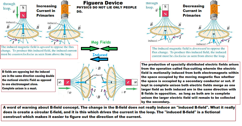 Regards, Marathonman
|
|
|
|
Post by Marathonman on Sept 7, 2020 17:50:41 GMT -6
Magnetic reluctance;
From Wikipedia and other physics sources.
Magnetic reluctance, or magnetic resistance, is a concept used in the analysis of magnetic circuits. It is defined as the ratio of magnetomotive force (mmf) to magnetic flux. It represents the opposition to magnetic flux, and depends on the geometry and composition of an object.
Magnetic reluctance in a magnetic circuit is analogous to electrical resistance in an electrical circuit in that resistance is a measure of the opposition to the electric current. The definition of magnetic reluctance is analogous to Ohm's law in this respect. However, magnetic flux passing through a reluctance does not give rise to dissipation of heat as it does for current through a resistance.
The term reluctance was coined in May 1888 by Oliver Heaviside. The notion of "magnetic resistance" was first mentioned by James Joule in 1840. The idea for a magnetic flux law, similar to Ohm's law for closed electric circuits, is attributed to Henry Augustus Rowland in an 1873 paper. Rowland is also responsible for coining the term magnetomotive force in 1880, also coined, apparently independently, a bit later in 1883 by Bosanquet.
Reluctance is usually represented by a cursive capital R. In both AC and DC fields, the reluctance is the ratio of the magnetomotive force (MMF) in a magnetic circuit to the magnetic flux in this circuit. In a pulsating DC or AC field, the reluctance also pulsates. magnetic flux always forms a closed loop, as described by Maxwell's equations, but the path of the loop depends on the reluctance of the surrounding materials. It is concentrated around the path of least reluctance. air and vacuum have high reluctance, while easily magnetized materials such as soft iron have low reluctance. the concentration of flux in low-reluctance materials forms strong temporary poles and causes mechanical forces that tend to move the materials towards regions of higher flux so it is always an attractive force (pull).
NOW to my point, Figuera did not close the path of his cores for a reason and that would be reluctance. Since reluctance is analogous to resistance i will give an example that might help in the understanding of reluctance in the Figuera device..
Constant air gaps can be created in the core of certain transformers to reduce the effects of saturation. this increases the reluctance of the magnetic circuit, and enables it to store more energy before core saturation.
The analogous electrical form of reluctance is resistance and is used to slow down current flow. If i had a low ESR capacitor and grounded it's terminals through a low resistance circuit, the entire capacitance would be dumped in a very short time causing things to jump and burn. Now lets take a large resistor adding it between the cap and circuit then connect the terminals. This time there is no jump and no burn because the resistance will not allow but a trickle of current to travel through the circuit. If it is high enough it may take hours to bleed off. it slowed the dissipation of the dielectric kinetic field energy.
Now back to reluctance, in the Figuera device there are opposing electromagnets with the South pole exposed as in not used. When the electromagnet poles are compressed and swept back and forth the path the flux must travel to get to the South pole is through air in which we all know is much higher magnetic reluctance (resistance) then that of the iron core. Just like the analogous form using a resistor, the magnetic field being compressed and stored in the area of the secondary has to travel through air to close the path of travel. This high magnetic reluctance path slows the magnetic flux dissipation down just like the bleeder resistor allowing the field to dissipate at a much slower rate which allows the magnetic field to retain a high field strength while being swept back and forth.
The rising primary at it's peak has to travel a much longer magnetic reluctance path then that of the reducing primary which allows it to retain much of the stored magnetic flux energy at it's peak in the field rather then dissipating it immediately. Thus Figuera used both primaries to compress the magnetic flux lines to a high intensity then used the long magnetic reluctance path to resist the dissipation of said field which allows them to retain upwards of 90 % of their combined field while sweeping back and forth.
So all you people freaking out about the cores being open, please do not fret, Figuera has you covered and for a good reason. Please study reluctance and calm yourselves.
Regards,
Marathonman
|
|
|
|
Post by Marathonman on Sept 7, 2020 18:32:23 GMT -6
Here is to all those people that fought so hard to oppose me in my Figuera endeavor and refused to listen to the words i was speaking to this day.
"We must not judge by what a man says if we have good reason to know that what he means is quite different. To be quite
fair, we must conscientiously endeavor to translate his language and ideas into those we are ourselves accustomed to use. Then, and then only, shall we see what is to be seen."
Regards,
Marathonman
|
|
|
|
Post by Marathonman on Sept 27, 2020 19:47:11 GMT -6
As i have been saying when increasing the inductive Reactance current flow will decrease, while decreasing inductive reactance current flow will increase. the Variac uses this very same inductive reactance to control current flow as the Figuera device. the only difference is in the Variac the AC (alternating current) does the changing for you, in the Figuera device the brush does the changing for you, actively changing the circuit as the brush rotates..
in the graph below which depicts an increase in inductance which increases inductive reactance in ohms which therefore decreases current flow. the graph shows the frequency being steady while the winding count of Figuera's part G changes increasing and decreasing inductive reactance as the brush rotates. This next graph shows self inductance of a coil and it's associated magnetic flux surrounding the wire. if you increase the wire count per the same amount of current, the associated magnetic flux from increased linking will increase. according to Faraday any increase in magnetic flux produces EMF and according to the Lenz's Law the associated EMF will be in such a way as to oppose the original EMF reducing the original current flow. this is the basis for the Figuera device part G active inductor controller.
According to modern day Physics and Inductive Reactance "ANY change in current flow is considered to fall under inductive reactance". change the circuit, increase the magnetic flux, oppose the original current flow therefore reducing the flow, therefore giving current frequency thus falls under Inductive Reactance.
Regards, Marathonman
|
|
|
|
Post by Marathonman on Oct 10, 2020 15:15:28 GMT -6
Variable Self-Inductance;There are electric circuits in which the self-inductance is not constant but in which it varies as a result of relative linear motion or rotary motion between portions of the magnetic circuit ( Clemente Figuera part G). Relays, solenoids, and some types of electric motors and generators are examples of variable self-inductance due to one member moving with respect to another. When the self-inductance L is a variable Eq. does not express the induced emf because it does not take into account the time variation of L. According to Eq. the flux linkage is expressed in terms of self-inductance and the current by  A time variation of flux linkage inducing the voltage
This equation shows that there are generally two components in the emf of self-induction. One of these is L di/dt and is due to the time variation in the current, and the other, i dL/dt, is due to the time variation of the self-inductance.
EDIT; so this leads us with two possible scenarios of self EMF generation, one, a change in current over time or two, a change in self inductance over time. both produce emf yet it is the latter, a change in self inductance changes current flow in the Figuera device.
*It is important to note that emf can be induced in an inductive circuit even when the current is constant if the inductance undergoes a variation with time.*
******OMG ! can you repeat that last statement according to Faraday Physics ?******
*It is important to note that emf can be induced in an inductive circuit even when the current is constant if the inductance undergoes a variation with time.*
imagine that ! i have been saying this for how many years now ? at least 5.
The self-inductance of Part G's electric circuit is the parameter that is associated with the flux linkage resulting from the current flowing in the circuit itself. this flux linkage changes as the brush rotates either expanding the circuit by adding loops, increasing it's self inductance or shrinking the circuit by subtracting loops, decreasing it's self inductance.
This magnetic flux linkage is either increasing or decreasing at all times as the brush rotates which is in exact accordance of Faraday's induction law in 1831 which basically states,"any fluctuation of flux either increase or decrease within a circuit will create EMF."
Thus according to Lenz's Law, any self generation of emf from flux linking will oppose the original current flow thus reducing the original flow by how ever many loops are added to that side of the system which increases flux.
One side adding, one side subtracting at all times within the time constant of part G which is the production of EMF within the two halves of the active inductive controller producing an EMF that opposes the original flow. Increase the opposition, the current will decrease. decrease the opposition, the current will increase thus an orderly rise and fall of current flow which has just been given frequency which then falls under inductive reactance.
Reminder, Inductive Reactance; "Any change of current falls under inductive reactance."
When an alternating current of constant amplitude or DC given frequency is passed through the winding of an air core or iron core inductor, energy is alternately stored and given up every quarter cycle in AC systems or in Figuera's part G every 1/2 cycle. If the resistance of the circuit is negligible, all of the energy that is stored in the magnetic field during one quarter cycle AC or 1/2 cycle of Figuera part G is returned to the source during the following quarter cycle AC or 1/2 cycle of Figuera. The average power consumed by such a circuit is zero for a complete cycle in the AC circuit yet is additive in the DC circuit. The supply potential plus the released potential combined.
Lets repeat that again, all of the energy that is stored in the magnetic field used to oppose current flow in part G is returned to the system and the power consumed is ZERO minus losses.But with the DC Figuera circuit they are additive of all supply potential and released potential. So i say again, how can Figuera device be self sustaining, I just did. 
Regards, Marathonman
|
|
|
|
Post by Marathonman on Oct 14, 2020 14:29:19 GMT -6
As i been saying, one must observe the spin directions of the magnetic fields to realize Figuera fulfilled the same EMF generation as a standard four pole generator yet using only two poles. Observing the below spin direction you will realize that when each primary is occupying the secondary one at a time the spin directions are in opposite directions thus the same as a standard generator.
The only difference is Figuera increased one and reduced the other to get the induced electric fields in coherency ie.. (the same direction) which is positive and additive unlike the magnetic fields that will always be opposing and in different spin directions.
Below is the spin direction of the magnetic fields. notice the induced is positive and additive in the same direction from one increasing and the other decreasing. Magnetic fields always opposing in different directions. Electric fields always positive and additive.
Regards, Marathonman
|
|


