Part G
When a person dives into the research of part G and studies Inductors, Inductance and Inductive Reactance you will quickly realize that every video and material posted by Physics Professors, Students and University Physics dept all point to the same conclusion and outcome that a steady state DC does not produce Inductance. While this is basically true it is NOT the complete information on Induction and DC current flow to say the least. If a person was to some how alter the aspects of DC to mimic the actions of AC current rise and fall then that person would then be able to attain Inductive reactance with DC which in turn control the flow of current.
Within the FACTS of this post I will in fact show that DC can and will control current flow which will then fall under the realm of Inductive Reactance.As stated by Universities in their postings and publication on Inductive Reactance it is stated on most if not all that and alternating current flow (AC) or any change in current will produce Inductive Reactance. Again I will replete that if you missed it ANY CHANGE IN CURRENT FLOW IS INDUCTIVE REACTANCE. For the remainder of thesis I will prove that the Figuera device utilizes Inductive Reactance to control current flow in Part G which in turn controls the current flow allowed through both set N and set S electromagnets.
The teaching of Inductive Reactance in every College and university around the world from Physics professors is a completely one sided thought that a change in current flow is the only way to control inductance. While this may be true for a completely static Inductor system it is completely false and does not apply to an active Inductor. Test research conducted myself on my bench concluded that when DC current is applied to an Inductor it will in fact have Inductive Reactance for the time constant of that said circuit until steady state current flow is achieved. When first applied the current is low from the Reactance of the magnetic field reversal to the original flow of current up to the point of steady flow. While this is a very short live Reactance we will have to change the perimeters of the circuit to get Inductive Reactance on a continuous basis.
In Inductive Reactance we have a current change that causes a change in Inductance known with AC. This is cause and effect and is what is taught in all universities around the world. What is not taught is with an active Inductor we have a change in Inductance, the magnetic flux to current ratio as the brush rotates, that changes the current flow in a DC system which is the cause and effect. Within the time constant of said circuit we change the loop count of either increasing or decreasing we are changing the magnetic flux within that circuit and according to Faraday in 1831 we will in fact produce an EMF and according to the Len Law it will oppose the original current flow. Any time we have a rise or fall of current flow what we end up with is giving the current frequency so within the active Inductor controller using Inductance to change current flow thus frequency has just been given to DC which now falls under the realm of Inductive Reactance.
Again, at any time we change the loop count on the core with a steady state DC current flow within the time constant of that circuit we will in FACT change the magnetic flux to current ratio which according to Faraday’s Laws of Induction in 1831 states any increase or decrease of magnetic flux will produce an EMF. Since the EMF was created within said circuit, it according to the LENS Law will oppose the original current flow that created the magnetic field in the first place. Each time a loop is added that loop magnetically links to the circuit and that magnetic linking increases the magnetic flux associated with that circuit. so any increase or decrease in magnetic linking to the circuit producing EMF is in exact accordance with Faraday’s Laws on Induction and the Lenz Law to oppose. Thus any change in current flow gives way to frequency irregardless if it is AC or ANY such change in current flow. Inductive Reactance initiated by inductance which in turn causes a current change thus given frequency thus Inductive Reactance.
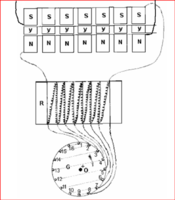
So according to these findings Part G Inductive controller in the Figuera device does just that. As the brush rotates in a circular manor having two feeds, one from set N and the other from set S will have a north face opposing fields at the positive brush. This opposing fields basically split the inductor in two halves of opposing field allowing the Inductive controller to control two separate feeds 180 degrees from each other yet remain in complete unison through the entire rotation of the brush. As one side of the brush is increasing the magnetic flux to current ratio, decreasing the current flow to that set of electromagnets. the other side is reducing the magnetic flux to current ratio increasing it’s current flow to that set of electromagnets.
So the basic concept and operation of the Inductive controller Part G is as follows
1. Two pole configuration N & S to regulate the output of it’s winding’s and the draw of the starting power supply.
2. Split the feeds into two allowing the control of two current feeds, one rising in current flow, one reducing in current flow in complete unison.
3. Store and release potential into the system to off set the rising side potential drop as it is storing into the magnetic field for the next half cycle. This basic operation is conserving, preserving or recycling if you will the excitation side of the system potential.
4. Forward bias the rising side of the system to allow more current to flow to replace the reducing electromagnet’s reduced magnetic field line pressure. This forward biasing allows the voltage to be increased in the system which in turn allows more current to flow boosting the rising electromagnet field line pressure which maintains a steady output.
5. Amplification, with the opposing fields in place is the perfect avenue to introduce the secondary feed back into the system thus elevates part G to the sole power supply of the system as the starting supply is removed. Also to replace losses occurred in the system and give rise to amplification to the rising primary. Part G can be looked upon as an amplifier, the three reduced potentials combined in part G to amplify the signal to the rising electromagnet.
Just try that without part G's core and tell me how it works for ya! part G has many functions that can NOT be simply replaced with electronics thus the use of a closed core with Inductive winding's is a must.
Since all coils on earth have Inductance both parts of each half of the system (Increasing, Decreasing) are a vital part and function of the system. When the reducing half of part G is reducing at the same time the reducing set of electromagnet are being reduced also. Since they are not connected in Mutual Induction their individual reduced magnetic field potential is released into the system and combine in Part G like two batteries in series. With the added secondary feedback into part G, these three potential combine to raise the voltage in the system to offset the rising side of the system that is storing into the magnetic field increasing it’s field line pressure. This added boost from the secondary feedback gives the rising electromagnet the needed field line pressure to replace the reducing electromagnet drop in pressure that is needed to get the sweeping action across the secondary. This added boost is an amplification in potential to the rising electromagnet which then is able to maintain the required pressure between the two opposing electromagnets to maintain required pressure needed for your output.
Electromagnets
When Clement Figuera designed his device the first one was a rotating device that was possibly shaped like the egg of Columbus. Later in his patents he refined the device to stationary yet to him it still needed further refinement. These were his 1902 patents which were modeled, as his 1908 patent, after the rotating generator of that time period. Every rotating generator produced by man has the unavoidable need to rotate a huge mass of iron which is plagued with massive clogging effects as it approach and recede from the stater. This clogging effects if the unavoidable reverse torque imposed on the rotor which is the Lenz Law hard at work. This reverse torque is why it takes 150 % power to rotate the generator to receive 95 % power from the system when power is drawn from it. What amazes me is this is all man has achieved in the last 150 years of progress or at least what the powers that be will lead us to believe is so which in reality is a complete fabricated lie to maintain their cash flow from our hands to theirs.
In the Figuera device he studied a rotating generator and came up with a solution that allowed him to forgo the rotation, eliminating the cogging effects from the Lenz law which leaves the stationary generator much, much more efficient then that of standard junk on the market. He figured out that with opposing electromagnets he could raise the field line pressure to match that of the standard generator north and south high intensity field without the two fields combining as one field. With these opposing primaries he then reduced one electromagnet while increasing the other to get the sweeping action across the secondary that was positioned in between them.
When the primaries are powered up the secondary has no residual magnetization so the primaries have to polarize the secondaries. in doing so when current starts to flow in the secondary and the load the secondary will form an opposing field that will oppose the original current flow. When this happens the secondary and the primaries part ways and it is just the relative motion of the primaries that induce motion into the secondary. This action is similar to a squirrel cage motor when the primaries polarizes the secondary bars and current begins to circulate a second field is formed opposing this change. They then part ways, which then it is just the relative movement of the primaries that induce the secondary. After that no power is transferred to the secondary. after polarization takes place there ceases to be any such magnetic linking between the primary and secondary remain so throughout it's operation.
With the secondary opposing field formed that is between the opposing primary north face fields it is shoved from side to side by the rising electromagnet. To get the sweeping action the entire length of the secondary, one primary is reduced and in doing so creates an electric field in the process while the rising primaries shove these opposing fields of the secondary and the reducing primary across the secondary. Again with this newly created field the opposing secondary is at the same time shoved across this electric field to one side of the secondary giving the illusion of motion to this electric field thus creating a Motional EMF in the secondary. At no time after polarization is energy transferred to the secondary as it is just the relative motion of the sweeping primaries that induce the secondaries.
This whole action of this device falls squarely on the shoulders of the Inductor Controller Part G that has just enough inductance to get the sweeping action of the primaries. The reducing primary is reduced with just enough inductance to sweep the entire secondary and to just clear the secondary then back to full potential as the other primary is reduced to get the sweeping action to the other end of the secondary. If this action is not followed then the output of the secondary will be reduced substantially as will the use of a 1 to 1 ratio of primary to secondary. The field line pressure required can NOT be maintained if the primaries are not substantially larger then that of the secondaries and is shown in the 1908 patent which was confirmed on my research bench to be true.
“R” and Commutator Bars
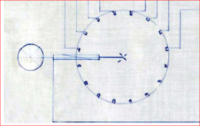
as per the 1908 patent the use of resistance and wording in the system is used to control current flow. As stated specifically “R” is drawn in it’s elementary manor to facilitate the comprehension of the device only as is the commutator bars. Why people are still so darn determined to hold on to the illusion that “R” exists as a separate entity is completely insane beyond belief. “R” in it’s higher form is the actual Inductive resistance of the wire wrapped around the core as the brush rotates. The very notion that an astute Physics Professor and Forestry Ranger would use heat death resistor in a fabulous device like this is nothing short of pure ignorant insanity. Especially considering the potential once converted to heat is NON recoverable as in lost forever. Their is no “R” and it does NOT exist as a separate entity yet resides between the wires as the brush rotates around the Inductor controller part G.
Commutator bars are in the same class as “R” and again are not used in the original device yet is fine for the description of the device for the comprehension of it’s operation as was “R”. why would an Astute Physics Professor use very thick and large chunks of copper bar embedded then turn around and connect them with puny little low current wires. This again falls under the complete insanity realm which is the complete opposite of what a builder of the most fantastic device in this century would do. The contacts Figuera is referring to is the actual thick wires looped around the core with a brush that rotates making contact with more then one at a time. If the so called commutator bars were used with the roller brush Figuera shows in the patent then it is impossible for the roller brush to make contact to more then one commutator bar at a time. Since part G was made in Germany and it just so happens that Zeiss was in Germany the likelihood of Part G being made by the experts in the industry Zeiss and it’s partner Abby is well into the high 95 plus percentile reality that Zeiss did in fact make the controller. Another compelling clue was Abby of Zeiss used roller brushes in his E I controller to control the light in his microscopes that he invented. It just so happens that the drawing of the 1908 Figuera patent shows a roller brush in all it’s glory.
My conclusion of my research is “R” does NOT exist as does the commutator bars and were just used to get the description of the device and it’s operation across to the patent office only and to obscure it's true form.
To plan your Figuera device build you need to decide on what your power requirements are then calculate the secondaries needed for that output without overheating in the process with additional headroom. When the amount of flux is calculated to maintain your output as per your secondary count that amount is split between your primaries so each primary is accountable for half the flux of the secondary output. Then Part G is calculated as each half of the system is calculated separately with added headroom remembering that the reducing primaries are only taken down to “just” clear the secondary then back to full potential. Another thing is to remember is the brush is rotating at 3600 Rpm for the US and 2500 Rpm for other Countries and when the full power of the system is flowing at the peak of the rising electromagnet it is only on for microseconds at a time which is not near enough time to cause heating of the wire.
Another thing to remember that Part G becomes the power supply so wind accordingly assuring part G can handle all the sums of the lower parts plus headroom just like any standard power supply would need to be. The use of thicker wire reduces IR2 losses occurred in part G increasing it’s efficiency of not only part G but used in the primaries also lowers the resistance of the primaries allowing them to react as quick as they can from the current changes of Part G allowing them to do their specific job of being an electromagnet. Remember part G controls the current flow NOT the primaries. Over redundancy and added resistant losses is not needed.
So from this report the question will arise Can part G be wound on another type of core and the answer to that is definitely 'YES' as long as the core is a closed core so the magnetic fields can be conserved, preserved, recycled or confined if you will within the core and not lost through flux leakage as with an open or straight core. As long as the brush can rotate in a circle making contact with more then one contact at a time and with the proper amount of Inductive Reactance for current reduction you will be just fine.
Regards,
Marathonman