|
|
Post by Marathonman on Sept 16, 2019 18:28:39 GMT -6
The whole idea is splitting the supplied current to feed the two inducers then increasing one then reducing the other to get the sweeping action in the space occupied by the secondary. Each opposite flux occupying the secondary at different times in opposite direction. The compression of the field lines increases the induction potential to match that of a high intensity north south field of a standard generator. Upon each sweep of the electromagnets one is filling the secondary with flux while the other is being removed having the same reaction as being rotated through a NS-SN field. As the flux of the reducing electromagnet is being removed the rising electromagnet being behind the opposing secondary fields is filling the secondary up with opposite flux and vise verse on a continuous basis. both opposing fields add to the total flux seen by the secondary.
The field line pressure is maintained at all times as the reduction of one electromagnet to get the sweep is reduced just enough to clear the secondary then back to full potential which retains a very large portion of the entire flux in the secondary area. The higher the flux potential is maintained the higher the output will be that is why reducing to far you are loosing a lot of flux in the process and your output will plummet.
Since the system uses DC to excite the primaries they maintain a very strong magnetic field. When reducing the fields are not reversing yet the coil on the core will see the magnetic field being pushed/retracted and produces an emf that is sent to part G to aide the system in forward biasing the rising primaries to maintain the pressure between them. The entire process is all about filling up the secondary with flux then removing that flux while the other opposite flux fills up the secondary only to be removed again. Any increase in voltage in the system will forward bias the rising primaries allowing more current to flow giving rise to amplification fore which i have posted on that with Ohms Law graphs.
At no time after polarization will the primaries or the secondaries magnetically link to each other other than soft couple to the reducing electromagnet so while the reducing electromagnet is reducing the electric filed it creates is free to induce the secondary at no expense to it or the rising electromagnet. No transformer action, no linkage, no reduction of inducer potential, no drag, 100% output, 100% excitation potential conserved minus some losses occurred all through the use of an Active Inducor Controller that conserve it's potential unlike a heat death resistor of unrecoverable losses.
If you still think "R" is a separate entity and is resistor or resistors you might want to switch planets because on this planet earth, Figuera uses an active inductor to control current and conserve potential.
Regards,
Marathonman
|
|
|
|
Post by Marathonman on Sept 17, 2019 23:22:43 GMT -6
AC Sinewave Output
The entire reason for having the ends on longer then the ones in the middle is from the inductive roll off to the secondary. With the rotating brush the ends are on ruffly three times longer then the ones in the middle and since the primary induction is dependent on constant changing current flow. The induction from the primaries to the secondaries at the ends being on longer will begin to loose induction from the hesitation. The current flow has not changed but the movement of the magnetic fields from side to side is delayed which will cause an inductive roll off of the secondary. By the time the roll off starts to curve downward the brush is rotating to the other contacts which will continue the downward slop as that primary is being reduced. this action causes the nice sine wave we need for our output. If this did not take place and the primaries zipped right through the ends like the middle contacts then the secondary would output a saw tooth wave not a sine wave. This is why i have been harping on the ends on longer in the electronic switching to get this nice sine wave output plus the channel overlap for Make Before Break to eliminate current interruptions. Shutting one channel off then turning on another will cause Bemf that will kill the device, everything has to be nice and flowing. With the rotating brush this is an automatic function as the brush rotated through it's contacts in a ring like fashion. You can look at one of my earlier posts where i posted a shot of part G with a rotating brush or roller brush and you can plainly see the ends will be on for much longer then the ones in the middle. this will cause the exact reaction previously described in the upper part of this post. MM |
|
|
|
Post by Marathonman on Sept 23, 2019 16:32:51 GMT -6
There isn't any one way to build this device as many people have different ways of doing things with likes and dislikes. The Figuera device is just the same and can be built in many ways being no set path or order as long as the fundamental operating principals are followed. Take for instance the primaries, if you wanted to build a small test unit that putout 1,000 watts with a ratio of two to one primary/secondary, it can be easily scaled to 5,000, 10,000, 15,000 using the same principles and scale you used in the first.
As long as part G has enough headroom you can add additional triplet sets as you want within certain reason as long as the output requirements of part G can handle the load requirements of the primaries. always remember, PART G controls the current flow and becomes the power supply once the starting is removed. My health has improved very much with the help of some very kind neighbors i have now so it will not be much longer that i will be able to continue my build. I soooo look forward to this. Regards, Marathonman |
|
|
|
Post by Marathonman on Sept 24, 2019 13:36:33 GMT -6
Is it a Core or Support
In the 1908 patent it shows just the three core sets N, S and Y, Y obviously being the secondary output. what is not shown is the cores being secured in any way in it's location as the opposing field pressures would push them apart. In the subsequent patents filed by Buforn after Figuera's death (which in today terms would be a patent violation) he spilled the beans as to say exposing a little more information in the patents. What i am referring to is the patent picture of the cores themselves. Even though the patent clearly indicates it is just a drawing for understanding purposes which i think applies to part G and "R" only as per the description. The cores are actually never mentioned except as N, S and Y rectangles. At first, back in 2013 i actually thought the bar stretched across the three electromagnets was a iron core which looked rather odd. i thought to myself why would Figuera do that with only part of the core in the primaries as this would be foolish. Well after further study and observation of all the patents they clearly show this bar except the 1908 patent which exposed just enough information to get the patent only. the bar is shown extending from one primary across Y then to the other primary. Think about this for a moment, why in the world would this bar be on top of all thee cores yet not be described in the patent in any way, shape or form. Please observe the picture paying close attention to the bar which is actually on "top" of the cores.  Answer to the puzzle; Answer to the puzzle;The bar (non magnetic) in the patent pic can only be there for one purpose and one purpose only, and that is to hold the electromagnets in place. Since the electromagnets will have substantial pressures between them wouldn't it be wise to hold it in place to not break them or hurt someone. If someone was standing over the cores looking down the pic above is what they would see if the bar (non magnetic) was in place to hold the cores. In light of some new information i have come across and of which was purposed by a member years ago on EF but was quickly dismissed. Upon further studies and research i was only going to expose this information only after i have substantiated this claim through verification. What is purposed is that the bars on the cores are there to hold the electromagnets in place after tuning or balancing of the two primaries with a preset gap for balancing. This way they are held into place as to not detune after set. When the two electromagnets are opposing with the opposing secondary field sandwiched between them, one is reduces, the other increased, to get the sweeping action of the secondary. The reducing primaries magnetic flux has to be completely removed from the secondary core otherwise any remaining flux will reduce the output by the same amount. At the same time this action is taking place the rising primary is filling the secondary full of flux behind the opposing secondary field. In order to get the entire secondary area completely filled with flux the secondary opposing field must pass the end of the secondary in the space between the cores that way the rising primary can fill the entire secondary then when reduced it will create an electric field the entire length also. One of the test performed by a member on the sweeping of the fields produced a double peak on the secondary output with the cores touching each other. The double peak was caused by the secondary field leaving the electric field and entering the reducing primary core. This double peak is not suppose to happen in the Figuera device and can cause problems with the opposing field pressure. So then the notion of a gap between the primaries and the secondaries becomes a valid claim as to eliminate the double peaking of the secondary and also explain the use of the non magnetic bar across the cores to hold the electromagnets at a specific predetermined length dictated from the tuning of the system. Obviously the gap is over exaggerated in the patent as the compress secondary field will not be that wide so the gap will be smaller. Although i have not verified this personally just yet due to past health issues you can bet your backside i will jump on it the first chance i get to verify it, unless of course someone else beats me to it. Regards, MM |
|
|
|
Post by Marathonman on Sept 25, 2019 20:50:03 GMT -6
FIELD LINE COMPRESSION
The Figuera device uses opposing fields in it's operation of which utilize the compression of the two fields to increase the field line pressure which increases the electric field thus the output. What it also does in it's highly compressed state is bulge the magnetic and electric fields in the area occupied by the secondary. What this means is a person can take advantage of this extended induced potential area by increasing the size of the secondary beyond the size of the primaries coils diameter. This technique of winding the secondary larger then that of the primary will take advantage of this extended field flux region thus increasing the output beyond a standard diameter coil. This would also open the door for several types of winding techniques to series/parallel all on the same core. It all depends on the builder and the intended voltage/current output desired. Below is a graph from an on line magnet store which depicts the opposing magnetic fields extended region that the builder can take advantage of. If it is there, why not take full advantage of it increasing your output. It's that simple. Remember this is magnets producing the bulge, electromagnets being stronger produce a field that extends out farther. The purple area is the sweet spot for the secondary as the field line compression is at it's highest then reduces by square of the distance. Notice how fast the field lines expand out reducing the pressure of the two opposing magnetic fields from very intense pressure to very little pressure. EDIT;If a builder had one set of electromagnets at 14.8 lbs psi (1 kilowatt) the purple area below would be at 14.8 lbs per square inch so wind the secondary to take advantage of this larger compressed area. It would be safe to say that if the below cores were 2 inch diameter then one could have a secondary coil of almost 3 inches to take advantage of the magnetic bulge increasing your output considerably.Regards, Marathonman 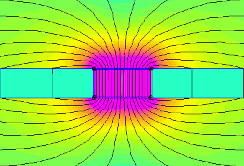 |
|
|
|
Post by Marathonman on Sept 27, 2019 12:43:45 GMT -6
When dealing with the design and construction of the primary coils some details have to taken into consideration even though i have posted information on the primaries, i am hitting on that subject again.
As stated previously the primaries are not wound like present day "authorities" (what a joke) suggest using resistance to control current flow. Since part G controls the current flow why add more complexity or more resistance to the device then need be when more resistance leads to MORE LOSSES. The whole design and function of this device resides on the fact that it is highly efficient because of such extremely low resistance of the device as a whole. The device uses Inductive reactance to control current flow through the primaries not resistance that leads to nonrecoverable losses. this fact of current control is the most efficient way to control current on the planet hands down with very little losses. The member Peter found this info in an old book that has the time constant of a circuit explanation with calculations. thanks Peter. 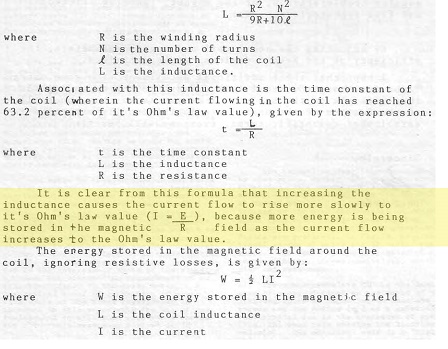 What this tells you is that if you increase the inductive value of the circuit you will increase the time constant of that circuit which slows the reaction time to current change. If you were to wind your primaries with one long length of wire, not only would you increase the resistance but also the inductive value of the coil which substantially increases the time constant of the coils reactance to current changes within the system set forth by part G. Since part G is the master controller of current flow throughout the system would it not be advisable to wind the primaries to work with the master controller with the ability to react instantly to any and all current changes all while NOT trying to control current them selves. Again why add more complexity then need be. I would strongly advice people to wind their primaries with as little resistance and self inductance as possible. In order to react instantly to any and all current fluctuations which one would employ such winding techniques as series and paralleling such winding's to take advantage of this time constant increase and reaction to such current changes. It does not matter if you use 20 parallel winding sets on your primaries as long as the total winding count adds up to the total flux needed for your field compression to satisfy the demand of the secondary output. The more you parallel the less the resistance/self inductance...ie the faster the response time the lower the time constant of the circuit. Regards, Marathonman |
|
|
|
Post by Marathonman on Sept 29, 2019 13:08:12 GMT -6
As the readers, members and builders alike have gathered from my research, studies and tests that even though part G is an Inductor it assumes may more rolls taken from a plain static device as used in present day which is continuously taught that way, to an active device that is the center for many very important function that are vital to it's operation. No where in history during my studies have i come across the use of an inductor in the active position. Plain and simple Figuera was a genius to conclude such use of this device would assume multiple functionalities all within the same time frame from one such single device.
The most confusing aspect of this device is the actual patent it self which was worded in a vale of secrecy exposing just enough information to get the patent yet keeping the vital functions of the device in darkness and uncertainty obscuring it under the elementary guise of "R" and Commutator bars. The patent description is as such worded from the actual working aspects that are broken down to it's elementary form for understanding only which in it self opened the door for much more confusion and wrongful interpretations. The second description given is the most accurate identification given of the three descriptions in the patent which is a ring distributor.
The commutator bars as such are used in the patent to represent contact which have an ongoing position change from the rotating roller brush. As the patent gives multiple scenarios fore which to call the function it represents, it can easily be misrepresented in it's actual form which is nothing more then the brush making contact with two winding's at a time as it rotates. (ie. Make Before Break)
"R" which is the representation of some resistance, is broken down from it's higher form of inductive reactance which is the actual wire looped around the closed core to shown having some resistance in the system to get the variation of current to the two sets of electromagnets. The actual elementary form shown on the patent has literally confused many unsuspecting researchers and readers to the extent that "R" in it's elementary form actually exists. Sorry but you would be incorrect in your assumption as common sense dictates the non usage of resistors which are extremely inefficient, wasteful heat death (non recoverable) devices as opposed to an unbelievably efficient Inductor controller. I rest my case on facts a lone not even including bench test results which solidifies the case against resistor usage. use resistors the device will NOT self sustain period.
The description in the patent given is actually a rotating roller brush that rotates in a circle fore which Figuera calls a cylinder or ring if you will. It makes contact with multiple loops of thick wire in which Figuera call commutator bars and "R" a resistance.
Quote:
" The operation of the machine is as follows: it has been said that the brush “O” rotates around the cylinder “G” and always in contact with two of their contacts."
The cylinder which he describes also as a ring distributor in the patent is his entire focus of attention through out the patent focusing on the rotation of the brush only which he calls a cylinder or ring distributor if you will. He does not include the rest of the device for the most part only the actual brush travel. this is of course the controversy fore which stems the massive confusion.
Quote;
“O” closes the circuit in each of the different contact until finished those in a semicircle, and begins to operate in the other half, which are directly connected to each other. In short, the resistance makes the function of a splitter of current because those current not going to excite some electromagnets excites others and so on." " One of the ends of the resistance is connected with electromagnets N, and the other with electromagnets S."
Figuera just described his focus of attention in the patent being contacts of commutator bars, ring distributor or cylinder as two halves, one being the upper semi-circle, the other the lower semi- circle or even the northern semi-circle and the southern semi-circle if you will, which "could" be the reason for the N & S sets of electromagnets naming convention which in it self is the center of many controversies. I myself have no controversy as i know the N & S is of course opposing fields.
Of course the second semi-circle is directly connected to the first semi-circle because the the connection is the actual wire looped around the core which again along with commutator and "R" in it's elementary form is the center for massive confusion to this day.
The actual device Figuera used in his 1908 patent is an active single layer inductor that utilizes inductive reactance to curtail or control current if you will in an orderly precise manor manufactured by Abby of Zeiss in Germany. At that time Abby's devices do NOT utilize commutator bars in any such fashion thus using a roller brush making contact with two contacts at a time to alleviate sparking in his AC variac controller for his microscope light control. Because Figuera used so much secrecy throughout the construction of the device it would be safe to say Abby know nothing of it's actual usage or the fact that it was utilizing DC throughout the system since each part was manufactured in different parts of the world.
Figuera utilizes a positive rotating brush to split the feed (Inductor) into two separate feeds (Opposing Fields) one increasing, one decreasing, 180 degrees out from each other as the brush rotates in complete unison. Each side utilizing it's own inductive reactance to control the current flow of it's connected electromagnets in a repeating cycle of rise and fall of current. Since the electromagnets are opposing, the magnetic fields are forever opposing in fashion irregardless of the current intensities within the two sides of the circuit.
In other words the DC induced magnetic field compression is constantly maintained through out the sweeping action irregardless of the intensity of current flow through the electromagnets (><). with each opposing magnetic field occupying the secondary at different times, filling then removing it's flux from the secondary, which i might add creates the electric field on the removal (reducing) of the flux within the secondary core. Then shoving the opposing secondary lenz law field across the newly created electric field at the same time with no such magnetic linkage what so ever like that of a transformer. Induction is then free for the secondary to take while the electromagnet is reducing imposing no such drain on the field of the electromagnets preserving or conserving if you will, the potential through out the exciting part of the system consisting of Part G and the electromagnets. The secondary and the load are of course a separate system.
So i will leave it to the readers, members and builders of whether to use heat death resistors which will render your device non sustaining or the use of an active Inductor controller that allows your device to self sustain. The choice is entirely yours.
Regards,
Marathonman
|
|
|
|
Post by Marathonman on Sept 30, 2019 13:46:04 GMT -6
Wow !, i can not believe after all this time i forgot to explain why the Figuera device uses two north opposing fields with a graph to illustrate. When using a north and a south high intensity field like that of a standard generator you have an intense field between the north and the south that basically combine acting as one intense field in one direction depending on the orientation or the N/S fields. this very reason is why the orientation of the poles have to be switched to get reverse flux direction and current flow in the secondary output. In the Figuera device you can NOT use the north and south poles as they combine as ONE FIELD IN ONE DIRECTION. So even if you alternate the current flow like Figuera does 180 degrees out from each other you will still get current flow in the same direction which is NOT AC. The fields will combine as one field so no separation of field direction. You also can not use ac to control this device as ac can not achieve the intensity of a DC electromagnet as ALL standard generators use DC to excite their primary exciters. Also using ac you have to flip all the domains which is very time consuming and takes a lot of power to do so. Even if you tried the domains will not all flip because the field changes direction before they can all flip. Very, very inefficient process. With two opposing fields using DC to excite the electromagnets will attain a very intense magnetic field, much more so then that of ac. Figuera used opposing fields to eliminate the transformer action that would take place in ac and also eliminate the magnetic linking to each other and to the secondary. With the two opposing fields having flux in different direction he was able to get flux reversal like a standard generator and increase the field line pressure at the same time to match that of a standard geny. So all that is left is to polarize the secondary, create the electric field to sweep across to be induced and to add motion to the secondary. By utilizing the opposing fields when one is reducing, the other increasing the reducing electromagnet creates the electric field to induce the secondary, the rising primary does the pushing, both being accountable for the pressure. Once polarization takes place and current begins to flow a secondary opposing field will form in the secondary (LenzLaw) and it is this field that is swept across the newly created electric field by the rising electromagnet. This motion of the secondary is sort of like virtual motion since we are dealing with a stationary system with no moving parts in the generating section. This virtual motion gives the secondary the illusion of motion to the electric field and EMF will then be generated. Irregardless if it is virtual or real motion it is just the same to the electric field as it sees a change in the secondary's opposing field position through "it's" spatial field relative to it's stationary position in space. Exactly like a standard generator according to physics something has to move relative to each other whether it is the electric field, wire or in Figuera's case the opposing secondary's field through a stationary spatial electric field. The rising primary is the motive force that induces motion into the secondary. Below is a graph illustrating why the fields can NOT be north and south with end result as pure Transformer action which is NOT the Figuera device as it is a generator. Observe the one way field using the Figuera style of switching. It is literally impossible to avoid combining of the fields which will cause the secondary to always link to them like a transformer. Shifting of the secondary then becomes impossible due to magnetic linking. Opposing fields is the ONLY way to avoid magnetic linking yet compress the field to a usable amount then shift to either side to induce motion into the secondary. Regards, Marathonman 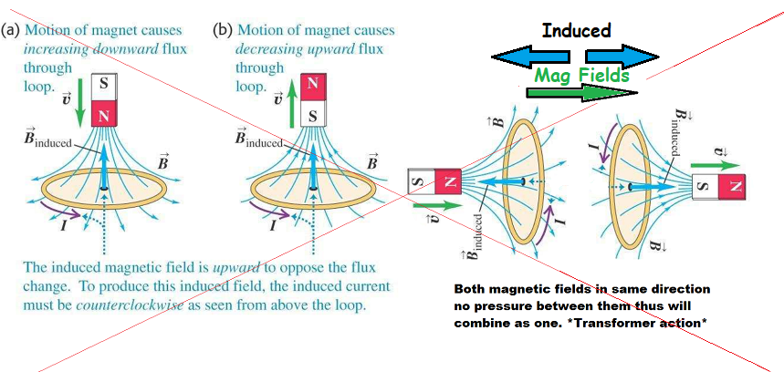 Below with the Figuera style of switching. notice the opposing fields which do NOT allow transformer action yet increase field line pressures thus electric field to secondary. 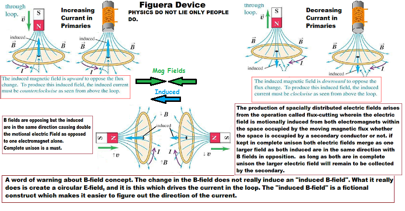
|
|
|
|
Post by Marathonman on Oct 4, 2019 18:26:35 GMT -6
INDUCTOR OR RESISTOR
I received an Email the other day and was presented with an interesting question. the question was, "How did you come to the conclusion that part G and symbol "R" were not separate and to the conclusion it was an inductor."? Well,
1. I was fortunate enough that i had someone share some very valuable information with me in 2013 - 14 that literally snapped open my eyes to real reality of things. 2. I studied inductance, self inductance, inductive reactance, inductor's reactions to AC currents, inductor's reaction to DC currents and so on which allowed me to formulate a plan of bench tests to substantiate these new findings and claims. 3. I studied the patent until my eyes bled referring the reaction of said claims to real world reactions of magnetism and inductance. So lets start with 1. Yes, I was really fortunate enough that the original replicator of the 1908 patent (which has a real working device) shared some really valuable information of the workings of the replication. through the years of research and certain tests the conformation of these claims were substantiated thus found to be true. Why did he share with just me you ask, well, i was the only one at the time that didn't have my head up my arse. So i listened to every word copying everything, studying for a very long time, bench work and research proved it was true and he did do what he claimed to do. I also had to fill in a lot of unanswered questions pertaining to the device that since i had little money it took a while to confirm everything. "Aside from that what was my real first clue to the realization it was inductance that controlled current flow?."
That has been staring EVERYONE in the face since 2010 which was actually "R". Look at the picture below and you will realize why i came to this conclusion. "R" was told to you specifically in the patent that it was "Drawn in it's elementary form for comprehension of the device and or operation only." So that right there just told you it was NOT a resistor and in fact it shows you it was an inductor from the start. A resistor is zig zag lines that represent a resistor fore which it IS NOT, what it shows is wavy lines or rather loops that are indicative of an inductor since from Oliver Heaviside in 1886 if not Praxii in France so Figuera knew exactly what he was doing when he used looped lines.. AN INDUCTOR staring you dead in the face drawn in an elementary manor to give the appearance or an association to some resistance for comprehension of the system. 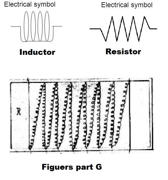 2. & 3. 2. & 3. So upon further studies of all the above i came to the conclusion (Physics backed mind you) that ac can not be used in this device because ac electromagnets are far to weak and just down right wasteful in the process of reversing the poles. AC had Inductive Reactance which controls current just fine yet with DC it only controlled current flow for a short time then elevated to full blown current after the time constant of the circuit. I then realized that all teachings around the world dealt with a static Inductor NOT and active Inductor so then the light bulb lit to the idea that since the brush is in a steady rotation the current will never have a chance to reach full current flow from the constant change of inductance. Each movement of the brush constitutes a change of inductance (Flux Intensity) (Magnetic flux to current ratio) on either side of the brush which correlates to the actual variable resistance of current flow of the two feeds. As per "Inductive Reactance" and i quote, "Any constant change of current flow can be can be considered Inductive Reactance" so while this device is DC it is constantly increasing or decreasing the magnetic flux to current ratio which is the opposition to the original current flow. So there for Figuera used inductance to control current flow which is then given frequency because of the constant rise and fall of current. Since we have a constant rise and fall of current with frequency it falls under the realm of Inductive Reactance so there fore Figuera's device part G and "R" is actually one device, An active Inductor that controls current flow of two separate current feeds on a steady basis as the brush rotates. Both feeds separated by two north opposing fields at the brush from two two current flows to the positive brush. YES ! current flows from neg to pos not the other way around. (study Ben Franklin's parody) Doh !These are facts (Physics) based on my findings on the bench which i have not created a video which i most certainly need to. Plus the fact that since i was broke at the time i instructed a member to wire a variac with DC to produce a video proving exactly my point as did Creasysee's video with 12 volt light bulbs. Both following the same principals outlined in this post and my research for the last 6 years. As soon as the rotating positive brush stops all ongoing Inductive Reactance ceases which then will let the current flow of both side increase to it's steady state minus the ohmic value of the wire involved. Figuera's device part G does not do that as it is in constant magnetic fluctuation of either of the two sides, increasing or decreasing using Inductive Reactance to control current flow which is initiated by a change of inductance not current change. The two are interchangeable but science hasn't figured that out quit yet or published it anywhere i know of. Doh ! So back to the original questions presented to me in the Email, I then asked, "Did that answer your question?" Answer, "YEP ! and then some, thanks a million". Bench tests do not lie, conduct them yourselves. learn it, confirm it, build it, spread it, it is the only way we can beat them in their own game. Only a ignorant fool would scream it will not work then resort to childish belittle games to discredit because those fools like on other forums (EF & OU) did not learn it, confirm it or build it to state otherwise. How sad for a grown man and supposedly a so called "Researcher" to do this which shows you can lead a horse to water, "But YA can't make em drink."Regards, Marathonman |
|
|
|
Post by Marathonman on Oct 6, 2019 17:30:56 GMT -6
SEPARATE SYSTEMS ACTING AS ONE
If you haven't figured it out by now Figuera's system is basically broken down into two separate systems operating as one system. One being the inducing system and the other the induced system which is the same as a standard generator. It also has a small potion of it's output (ridiculously small) to feed back to the input of the exciting system as does a standard generator to generate more output and to replace losses that occur. In the Figuera device the inducer system can be further broken down into two halves. Each half of the inducing system includes one half of part G and one of the inducer groups. Each half has two phases opposite of each other being the increasing/storing phase and the reducing/decaying phase. When one is storing the other is reducing and vise verse at all times. Remember even though part G is one large single layer inductor, it is being split into two halves with two opposing fields at the positive brush. This allows each half to act independent of one another all while being in complete unison. The entire length of the inductor will match your specific inductance required for your current reduction of your reducing primary to get your sweeping action and no more. I repeat, your length of your part G inductor and it's total induction must match the needed reducion of your reducing primary to get your sweeping action and NO more. Reducing to far will kill your output so if you require a reduction of 1/3 rd then the entire length of part G must reflect this induction. Each phase of each half is either in one state or the other relative the position of the positive brush on part G's winding's or ring distributor position. When the brush is heading towards set N away from set S, set N will be in the increasing/storing phase. The current to that side half of the inductor is increasing as is the connected inducer magnets which is also storing into the magnetic field for the next phase (increasing in intensity). The other half is in the reducing/decaying phase which along with its connected inducer magnets are reducing in current and releasing that stored potential into the system which offsets the potential drop of the opposite phase storing into the magnetic field. This storing will, according to physics, create a potential drop across the inductor. it must be replaced and the reducing side does just that. In the next phase the brush is heading away from set N towards set S as set N is in the reducing/decaying phase where it is now releasing it's stored potential to offset set S as it is now into the increasing/storing phase. It is increasing current to it's connected inducers and storing into the magnetic field thus causing a potential drop across leads which will be offset by set N and the connected inducers. Each component of each side will release or store it's potential in the magnetic field opposite the next half cycle. What seems to be some what confusing for some people is that when the half that is increasing in current flow the associated inductor winding's is reduced to almost nothing. The associated magnetic field is reducing in width but growing in circumference so it is said to be storing into the magnetic filed as the current is increasing. The opposite for the reducing side of the associated inductor as it is increasing in width yet reducing in circumference. It is increasing the magnetic flux to current ratio but reducing it's current flow at the same time. You can literally keep adding loops until the current flow is at almost zero but this is NOT what we want to do. This device is one of the only devices i know of that takes an boring stationary inductor, set's it in an active position in a system then spits the feed into two all while actively controlling the two feeds in complete unison 180 degrees from each other. Then on top of all that uses the stored and released potentials to it's advantage to transform the device to self sustaining. Part G is conserving it's exciting potential which allows this to take place, without it, say good by to self sustaining device. You will never get this to self sustain by electronics alone if going that route. the core and winding's of part G is absolutely a vital piece of the system. Regards, Marathonman |
|
|
|
Post by Marathonman on Oct 7, 2019 10:18:55 GMT -6
FIELD LINE COMPRESSION AND CORE RATIOS
The field line pressures between the sets of electromagnets can not be maintained if the ratio's are at 1 to 1. This meaning, if your secondary is the same length as your primaries the detectable magnetic field will project out by the same as the actual length of the core it's self. If you have a secondary the same length as your primaries then how on earth do you expect it to shove the opposing field out of the core if it is barely able to reach the end of the secondary's opposite end in the first place. I am sorry but this is not going to happen in a million years so those with a 1 to 1 ratio will get nothing for an output or very little there of. I have explained this may times especially on other forums which was obviously ignored as their brain got in the way and used a 1 to 1 ratio cores and then wonder why they have no output or rant this device doesn't work. I can not help from laughing at them as they are mostly lead by the rantings of fools that think they know all there is to know about magnetic fields as they were university taught and have a piece of paper to prove it. WOW!, this impresses me as much as their 1 to 1 cores do or like watching ridiculous vine video's on Youtube which i absolutely detest. watching some fool fluff their university feathers always get me laughing as they are so unaware of their parrot like nature they were taught to impersonate. Poly want a cracker status quo follower. With a 2 to 1 ratio the projected magnetic field lines will easily project pass the opposite end of the secondary which then can quite easily shove the reducing opposing field out of the secondary's core. Having these opposing fields with this capability can then be easily reduced to get the needed sweeping action of the primaries all while maintaining proper magnetic field line pressure. I have larger core because i already know this device works thus all i have to deal with is proper balancing of the primaries. You can definitely start off small as having some doubts as your knowledge of this device may not be at my level. It doesn't mater what size your cores are as long as they are at least 2 to 1 ratio. Starting off with a 2 inch primary and a 1 inch secondary will work out fine if you are under a budget constraint. 2 inch cores are cheap as is 1 inch so there is no excuse for the readers, followers or members for that mater to not join in the building process. I have dropped a lot of information on this site which is enough for you to get to where you need to go, much, much more then all the sites on the net combined. With a two to one ratio i see no reason why not, using the same set up, you can migrate at a later date to larger cores using the same part G as long as the overall va rating can handle the added load of the core sets. The reduction of the primaries will be the same whether the primary cores are at 2, 4 or 6 inches as long as the ratio's are maintained. Of course there will always be some adjustments made towards the balancing of the two primary magnetic fields. Remember always make exact copies of each other that way balancing is much easier. Regards, Marathonman 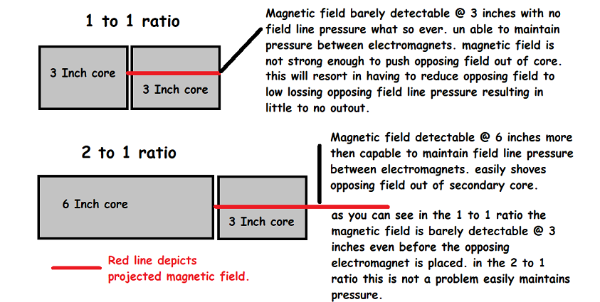 |
|
|
|
Post by Marathonman on Oct 9, 2019 13:56:35 GMT -6
Secondary feed back In order for the Figuera 1908 device to act just like a standard generator does it must employ the same techniques of feed back into the system. If not for the reverse torque of attraction between the rotor and the stator from the Lenz Law a standard generator would be an OU device. Why you ask, the feed back from the secondary is STUPIDLY SMALL compared to the output. Once the magnetic field pressure is met the draw of the inducers is reduced to just the IR2 losses of the wire. So when the draw on the output is increased it only increases the potential to the inducers enough to fulfill the output requirements then again is reduced to just the ohmic losses of the wire. Granted the pressure is still in the exciting system to maintain the magnetic fields yet is not being directly used by the inducers so it is circulated throughout the exciting system being conserved. If i remember correctly a standard generator requires between 10 to 15 % feed back from it's output and the Figuera device utilizing an inductor to conserve the inducer potential requires less then that. So with the Figuera device the secondary feed back into the system is needed to replace the losses that occur and to give rise to amplification to the rising primaries. again The feed back just like that of a standard generator is STUPIDLY SMALL in order to maintain the required pressure in the exciting system. remember this is a generating system so the feed back into the inducer system is generated and replaced over time so the need for large amount of power into part G is not needed as is exactly with a standard generator. Electric driven systems of man are a pressure regulated system that require a finite amount of time to build up the electrical pressure to a usable amount. It is a mere second or two to us yet is still required to build up to operating pressures in the system none the less. In the FIguera device part G becomes the power supply so it seems quite obvious that the secondary is fed back into part G to be added with the other reducing potential to offset potential drops and give rise to amplification to the rising primaries. This gives the effects of series batteries raising the voltage potential in the system to forward bias the rising primaries allowing more current to flow through them. Since the feed back is AC and part G is rotating it would seem quite fitting to add it through a commutator that way when the AC switches direction the brushes are at 180 degrees from the original position which allows the positive to remain at the positive brush and the negative to remain at the negative brush. This way the potential of the secondary can be directly added to part G which is where the starting potential is connected. The starting potential feeds part G which then circulates throughout the system until a working pressure is achieved. After this the system voltage is at a higher potential then that of the starting so it will be suppressed and can then be removed. The secondary feed back system consists of the secondary and the space or wiring between the two brushes as they rotate so as the positive brush is at set N the negative is at set S which is already releasing it's reduced potential into the system towards the positive brush anyways so they are all combined in the same direction. When the brushes are at the even point exactly between set N and set S the secondary will be at zero volts so there will not be any such direct grounding of the two terminal. The secondary feed back gradually increases it potential into the system peaking when the brushes are opposite from each other, positive at one terminal, negative at the other and vise verse. When the positive brush is at either set N or set S that is when the secondary feed back is at it's peak also. Please remember what the VERY gifted Sparky Sweet said in his research of the VTA that once the potential is stored in the magnetic field it becomes a separate energy quanta from the original current flow, so it is then bound by the inductor magnetic storage circuit which it will then travel around the circuit to get to the low pressure potential of the positive side of the inductor. What this is leading to is the system needs to be looped to the inducer inputs that way the starting potential and released potential can be built up to a usable amount in the system which then the starting can be removed. If it is releasing at one end of the inductors it must then be connected to the other end of the inductors in a loop otherwise there will be no potential flow. The starting potential is used until the working pressures are attained from the secondary feed back. The potential is generated over time which builds up system pressures over time this is just like a standard generator except the flashing (residual magnetization) is what creates the needed starting potential yet in the Figuera device the flashing has to take place every time it is started. The wiring of the testing phase and the wiring of the running phase are different and must be accounted for. the reason i have not ever introduced this information is no one has ever approached this level yet so i withheld it to minimize confusion. As soon as people start getting reasonable outputs i will post the last of the puzzle. Testing the system is quite easy as you have a positive brush and an inducer negative yet when you add the secondary feed back into the system it must be looped otherwise it will not sustain it's self. For testing purposes the secondary feed back is not needed and there is many other thing that are more important specifically the balancing of the primary fields. Getting part G and the primaries balanced are the high priority then and only then will you be ready for the secondary feedback and the looping of the system. there is no need to worry about the later until the previous is achieved first Ps. Once you get the balances right with the proper sweep you will know immediately as the output will jump through the roof. This includes the proper pressure between the primaries and the proper reduction of one primary to clear the secondary. Once there, you will know you have hit the sweet spot you can then make every set exactly like your test set which will then put out kilowatts of output. When you reach this point you will jump up and down with excitement like a little girl in a candy store. Trust me, you will so don't lie. Regards, Marathonman EDIT;Graph
1. Positive brush at set N is high, set S low, secondary feedback at set S is at it's peak forward biasing set N.
2. Set N & S even, secondary feedback is at 0.
3. Positive brush at set S is high, set N low, secondary feedback at set N is at it's peak forward biasing set S.
4. Set S & N even, secondary feedback is at 0.
All release and feedback potential is gradual over time, never plowing full of potential.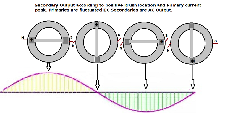
|
|
|
|
Post by Marathonman on Oct 10, 2019 14:34:10 GMT -6
Importance of Make-Before-Break
It seems that the make before break scenario is still not quite realized throughout the Figuera community. Some do get the reasons for it and some do not.
Lets discuss an example of a non make before break situation then apply that to the Figuera device.
suppose we are using a standard relay at 24 volts with a flyback diode in place with a switching transistor. When the current is flowing the relay is activated and the circuit is functioning just fine. The moment the transistor is turned off the magnetic field of the relay collapses and the voltage rises to an unbelievable 300 volts to keep the current flowing. With the diode in place the potential is diverted to the other side of the relays coil which is then dissipated mostly as heat. Without this diode in place the induction upon shut off hitting 300 volts is allowed free rain of the circuit which is trying to get to the low side of the inductor. In doing so it will completely destroy the silicone transistor in the process and possibly other ic's in the circuit. It's sole agenda is to equalize the electric pressure and will blast through anything to get there.
Just think of electricity as a spoiled rotten red headed brat that throws tantrums every time it doesn't get it's way. When not moving it wants to stay not moving, when it is moving, it wants to stay moving and if you dare disturb it in any way it will throw a terrible fit and have it's revenge.
Just think, that little tiny part created that high voltage and did all that damage with just a collapse of a small stored magnetic field. It you were within touching range of that 300 volts I will guarantee you will howl like a scalded dog.
Please keep fresh in your mind that ALL coils of any kind whether an air coil, electromagnets, Antenna or what have you irregardless if it has a core or not is an inductor. It will store a magnetic field, some more then others, some lethal some not.
Now lets apply the above scenario to the Figuera device. Here we have a rotating brush that makes contact with two or more contacts at a time in a Make-Before-Break to reduce sparking and have a linear rise and fall of current flow through two sets of electromagnets with a secondary feed back to self sustain.
If at any time there is a disruption of current flow through part G, the electromagnets or induction of the secondary BEMF will form just like the above scenario. Only in this case we have two halves of part G, 14 high power electromagnets and 7 secondary all screaming at 100 to 150 plus volts that will act just like the spoiled rotten red headed brat that will release all hell on you. I personally do not wish to play with that type of circuit. So in order to make your system behave properly i would strongly suggest you apply the Make-Before-Break scenario to your setup before you begin down the Figuera road.
Even though you might not experience that high a voltage i surely would not take the chance. With the proper setup you should get a nice linear rise and fall of current through your primaries with no current interruption with the simple Make-Before-Break setup that will also minimize sparking of the rotating brush. This is extremely prevalent in the electronic switching as any inductive kickbacks of this nature will definitely reek havoc on your IC's going poof ! in a nice curly puff of smoke.
Regards,
Marathonman
|
|
|
|
Post by Marathonman on Oct 12, 2019 13:16:45 GMT -6
ARE YOU STILL FUZZY?
I think the overall perception of part G is still rather vague or fuzzy in a lot of people's mind. The usage of resistors or resistance in general has been pounded so firmly into the minds of people from the misconceptions of Physics or rather the lack of a complete understanding as a whole there of. The same goes for transformer actions being separated from the actions of a generator which according to Physics uses the same so called mechanism for generating an EMF. I have seen on to many occasions people mixing the two as their understanding of how a generator or a transformer operates which in reality have two completely different actions taking place. The unfortunate side effects of an elite dictatorship society has literally left our our Physics understanding in complete shambles and in total darkness. Then on top of all that they only allow the professors and scientists to pass on the half ass truth of the real physical reality of things. how sad to put profit ahead of humanity enlightenment. The Figuera device part G is of course an active inductor yet is still so confusing to so many people because of the whole resistor/resistance concepts that resistance controls current flow that has been pounded down societies throat. So with this preconceived notion of resistance it is an automatic assumption that part G must be a resistor or resistor array upon sight of the patent drawing. He used resistance in the drawing to describe the principle of operation for ease of comprehension and states this specifically in the patent and it is time people wake up to this glaring fact. While part G does control the current flow it doesn't block it like that of a resistor which waste potential by converting it to heat to be burned off (transformed) as wasted potential nonrecoverable. Part G on the other hand directs current flow to either of the two inducers without burning it off as heat. The one amp current flow is split up between the two inducers which just so happens to use a magnetic field to efficiently split and control the flow of current in magnetic opposition. One amp of current is always flowing through the positive brush of part G irregardless of the position on the ring distributor or inductor. Granted there will be a slight rise at the peak of each primary as it shoves the reducing out of the core but in general the current feed is split between two inducers. Both inducers inductive fields combined equal the needed induction of the secondary output. I was reading on another forum where a self proclaimed know it all said the actions of part G is no different then that of a transformer. I almost died laughing, referring to the start of this post, he obviously doesn't even know how a transformer works either let along Figuera's part G. How in the world can you say a magnetic field being linked to each other literally sharing the same circulating magnetic field which drains the supplying potential is the same as Part G. Part G uses two opposing magnetic fields to split a DC feed into two separate feeds using Inductive Reactance to control current flow 180 degrees out from each other plus all the other actions i have outlined in previous posts. SO YOU TELL ME!, how on earth has this ANY relationship to a transformer in any way shape or form. It is quite obvious this loud mouth on EF doesn't know his arse from a hole in the ground and these are the type of idiots that are the opposer's to the Figuera device being self sustaining. Uneducated, total bias ranting opinions with no research what so ever to back up their claims. And you wonder why i enjoyed leaving such ignorant sites like that to pursue my own where i can post without such ridiculous uneducated rantings from fools that do not even know the difference between a transformer, part G and a generator let alone how to tie their own shoes.  While i do not claimed to know everything, i'm sure i know the difference between a transformer, Part G and a generator and it sure in hell isn't just an opinions based on wild ranting uneducated guesses.  Marathonman |
|
|
|
Post by Marathonman on Oct 13, 2019 12:54:47 GMT -6
DC verses AC with Electromagnets
Reversing magnetic domains wastes way, way too much energy. Having hysteresis, eddy currents, wire losses and core losses from trying to flip all the domains only to flip them the other direction before they are all flipped. wow what a waste of potential and time. The induced output is AC as the poles in the induced alternate each sweep. the induced does not consume potential of the inducers as the only consumption is the initial power used to establish the fields in the inducer magnets and to polarize the secondaries. After they start shifting they sustain themselves the same way any ordinary generator does with movement. You do not input current into a generator from a outside source while using a gas engine as a prime mover to generate electricity. All you do is pull the cord to start the engine and out comes the juice. As long as there is rotation or movement it will expand to it's effective limit and pour out the good stuff till you do something stupid or stop it. The real question you have to ask yourself is how does a generator work in the first place??? the reason i asked you this is that it does "In fact" get more magnetic field out then it started with even though no one added any current or greater field strength from an outside source. While the gas motor does rotate the generator, it's feed back is internal that will feed back until it is producing more potential then the primaries, secondaries and the load combined. Once the field is established the potential draw of the inducers is reduced to just the IR2 losses of the inducing system. The circulating current is there in the system to maintain the field yet is not being used directly by the inducing system. it is conserved. Figuera started his whole adventure by observing the existing generators of the time, then he made a solid state version fore which everyone can do the same. Just by looking at the movement in slow motion you will have a much better understanding of the parameters involved.
*Ask your self, how does the magnetic field increase and decrease in field strength as the rotor rotates.?
*Is there an opposing field from the secondary being rotated through the electric field.?
*How does the feed back effect the inducing system.?
*How is the inducing system electrically pressure regulated.?
*What happens to the inducers as they reach saturation.?
*What happens when a larger load is placed on the secondary. ?
*How is the generator able to start producing EMF from the start of rotation. ?
*Is the field intensity split between two inducers. ?
*Why does it take so much energy/force to rotate the rotor with a load. ?Reduce the numbers of the coils just to 3, because they are the pattern-base for every rotating generator, alternator or dynamos's of the day. You then apply all the answers to these questions with the information i have posted on this site, then you will find all your answers you are looking for in your replication of the Figuera stationary generator.
Regards, Marathonman |
|


