|
|
Post by Marathonman on Dec 16, 2021 13:01:41 GMT -6
Negative and Positive inductance
Considering the Active inductor controller that controls two separate feeds at the same time in complete unison 180 degrees from each other.. ie one rising one falling in current flow at a fixed frequency of 60 hz or other countries at 50 hz. Negative inductance
Can be seen as a capacitor which presents the same impedance as an inductor but with opposite phase of a normal capacitor. It is referred to as negative inductance when the stored magnetic field of the inductor is releasing it's stored potential into the system which is caused by a reduced current flow. The reduced current flow can not maintain the present magnetic field thus the reduction releases the stored magnetic potential into the system which in turn raises the over all system voltage. This is akin to having a short term battery releasing it's stored potential into the system as the magnetic field collapses interacting with the winding's in the circuit creating EMF. Positive inductance
Is the opposite which is when the current is rising and the inductor is storing into the magnetic field and as such there will be a voltage drop across the inductor. Even though the circuit on the rising side is shrinking in length, it is still storing into the magnetic field outward from the wire or circuit. With the present system of an active inductor having a rotating brush, there will be two opposing fields at the brush essentially splitting the inductor in two allowing Figuera to control two separate feeds at the same time ie,, set N and set S. With one side with positive inductance and the other with negative inductance and vise verse as per the rotating brush, the negative inductance will allow this device to offset the positive inductance voltage drop. Negative inductance = increase in circuit length ie.. increasing winding count thus lowering current flow releasing stored magnetic potential. Positive inductance = decrease in circuit length ie.. decreasing winding count thus increasing current flow storing magnetic potential. As you may have realized through my research and that of yours. a resistance, resistor or resistor network CAN NOT ever retain a magnetic potential in any way shape or form thus CAN NOT be used in the Figuera device. they are to wasteful of potential in the form of heat. it has to be an active inductor controller that stores and releases potential.
EDIT; This has to do with the primaries and part G. When power flows through both then reduced the stored potential in the form of a magnetic field when reduced releases that stored potential into the system. The primaries and Par G raise the over all system potential along with the secondary feed back which then gives rise to amplification of original stating potential thus surpasses and suppresses it since it is a higher voltage. It now no linger need the starting potential and can be removed.
Regards, Marathonman |
|
|
|
Post by Marathonman on Jan 2, 2022 17:49:45 GMT -6
THE REASON FOR THIS UNUSUAL SWITCHING IS TO PROGRESSIVELY ALTER THE RATIO OF THE CURRENT FLOWING THROUGH THE TWO SETS OF ELECTROMAGNETS WHICH IN TURN SHIFTS THE COLLISION POINT FROM ONE SIDE OF THE SECONDARY TO THE OTHER.
Figuera chose to use inductive reactance to control the ratio of current flow shifting current more to one set of electromagnets then the other then vice verse. In this process the storage of magnetic potential used in the control of current was in turn released back into the system when reduced increasing overall system voltage to offset the drop in voltage on the rising set of electromagnets. This is in fact the most efficient way to control current flow on the planet with very, very little losses compared to resistive currant control.
The excitation potential is thus preserved being first brought up to running conditions by an external supply then replacing small losses with the secondary feed back allowing it to continually operate by it's self from that point on. The reduction of the reducing side ie.. reducing electromagnets, 1/2 of the inductive controller and the secondary feed back increases the overall system voltage of the device thus negating the further use of the starting supply as the excitation side of the device is thus maintained in pressure.
Proper field line compression and specific sweeping from gap to gap only is the main key to energy production. Each electromagnet occupies the secondary one at a time in a progression to the other electromagnet giving the secondary output a true sine wave shape. The sweeping of the collision point is thus swept from gap to gap and no further along with the end being delayed slightly in time causing an inductive roll off just before it is swept back to the other side.
As i have stated before Figuera achieved energy generation like that of a standard four pole generator yet using only TWO POLES.
Regards,
Marathonman
|
|
|
|
Post by Marathonman on Jan 2, 2022 23:57:10 GMT -6
Negative voltage (inductive impedance)
This is what is being created as the active inductor controller expands and contracts both sides of the circuit. Adding or subtracting loops within the time constant of the circuit will create inductance as each loop added magnetically link adding to the inductive reactance of that circuit. Therefore the current being exposed to a larger negative voltage (ie CEMF/Back EMF) will reduce in current flow. The end result is giving DC AC like qualities of increase and decrease current flow thus falls under inductive reactance which we all know will control current flow just like an AC variac except with DC.
The loop area is the primary physical effect that controls the amount of inductance a current will experience. Increase the loop count, increase the inductance thus increase the inductive reactance reducing current flow. If we induce a time-varying magnetic flux in the circuit, there will be a time-varying inductive reactance within the circuit thus decreasing the original current flow.
The permeability of part G's core will reduce as the current is increased and as such the closer the saturation level of the core the less an impact it will have on the core reducing the released potential allowing the core in a sense to govern the amount of secondary output and feed back that can feed back into the system. This is why I have stated the core needs to have a little headroom just not to much that allows to much feedback and frying the device.
Regards,
Marathonman
|
|
|
|
Post by Marathonman on Feb 7, 2022 13:37:22 GMT -6
Active Inductor Controller
In the graph below which is just like the original patent except the original patent does NOT show the whole core specifically just the brush rotation and worded as such. In this graph I have outlined the on time for the ends and one of the contacts in the middle. As you can plainly see the ends are on considerably longer then the ones in the middle. The ends are like four to five times longer as I have been saying for many years. Also in the original patent it "SPECIFICALLY" says that the brush is making contact with two contacts at a time for a make before break scenario to allow the ongoing current rise and fall without any back emf collapse of the magnetic field in part G. In order to get the proper sine wave shape Figuera used his core design brush rotation to have the ends on for longer giving his output a nice sine wave shape. This equates to an inductive roll off because of this pause at the ends causing the induction to start to recede naturally giving it a nice rounded shape. As the brush continues it's rotation around the northern semi circle it naturally continues the reduction as the winding count increases to set N connection and decreases for set S connection. As my point exactly as I have been saying in order for the electronics to mimic this feature exactly as it applies, you have to account for this by allowing your electronics to have an on time of four to five times longer to allow for the inductive roll off just like the original patent. Not only that but the make before break feature is also a ( MUST HAVE FEATURE) in your design. In my attempt to mimic the feature ( which is being highly overlooked) I incorporated the make before break and the ends on for four to five times longer to mimic the natural built in feature of the mechanical brush rotation into my electronic and coding output. My electronic switching mimics these features " EXACTLY" as I intended to do so from my years of study of this active inductor controller. As you build either the mechanical which has these features naturally built in or electronically, you must incorporate these into your design in order for it to function as the original patent. The blue lines represent the area of contact and the time spent on. 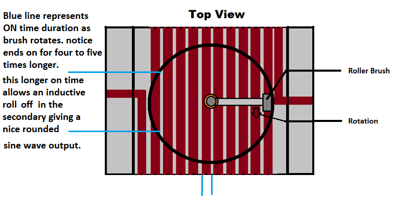 Regards, Marathonman |
|
|
|
Post by Marathonman on Mar 26, 2022 15:39:05 GMT -6
Superposition and Vector Potentials.
According to present day Physics the principle of superposition states that every charge in space creates an electric field at point independent of the presence of other charges in that medium. The resultant electric field is a vector sum of the electric field due to individual charges. While I am "NOT" a fan of electric charged particles in space or counterspace this is not my point of relevance to the topic. Since everyone should know by now that when ever there is an electric field there is a magnetic field and vise verse. Since the only way to combine magnetic fields is to align them north to south taking two magnets placing them together will make one large magnet. Placing them north to north or south to south obviously will be opposing. WHY ARE THEY OPPOSING?Quite simple, spin direction. Two north or two south poles have the same spin direction when side to side yet when put face to face they have opposite spin directions there fore will oppose one another. So one might conclude that independent magnetic fields opposing in fashion will never combine. Agreed!, but in all actuality there is a negative voidance at the south pole charging into counter space and a positive discharge into space at the north pole. Technically the voidance is the cause of the attraction not magnetic attraction as per Eric Dollard. Yes Voidance "charge" "S" and Discharge Positive "N" have spin direction. Which direction do the north and south pole rotate. South Spiral inward CCW (Charge into Counter Space- ie Voidance) and North spiral CC outward into space (Discharge) yet both spin same direction from above.  But I must also add that opposing magnetic fields when increased in strength can compress magnetic field lines much higher in intensity then that of a single magnetic field by a substantial margin. When dealing with electric fields in a superposition situation can and will be additive or their vector potentials if their sum's are in alignment or simply put, the same direction. This case scenario is completely applicable in the Clemente Figuera device. Magnetic potentials in opposing fashion will always oppose, but they are not being increased at the same time as one is increasing and the other decreasing causing their associated electric fields to be additive or aligned in the same direction. So when the associated magnetic field lines are being compressed so are the associated electric fields. This is why most misunderstood my graph below. notice the vector potentials of both magnetic and electric fields. Superposition comes into play here as does the vector sum of the electric fields. The Induced is the sum of both electric vector potentials in the same direction. One magnetic field is increasing yet the other is decreasing reversing the electric field to align with the increasing electromagnet's electric field or vector potential. 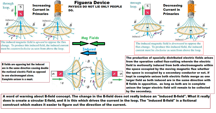 I will add to this as time goes on. Regards, Marathonman
|
|
|
|
Post by Marathonman on Aug 19, 2022 13:48:35 GMT -6
Sweeping Fields and the Electric field Created
Pretty much self explanatory but I will explain: Both electromagnets increasing and decreasing 180 degrees out from each other create an Electric field in the space occupied by the secondary. The electric field becomes as if one field as both induced are in the same direction. The secondary is polarized and current begins to flow with a load attached. According to the Lenz Law a second field will form within the secondary opposing the change. It is this opposing field that is pushed cross the secondary area electric field by the rising electromagnet. Since the reducing electromagnets is soft coupled to the secondary opposing field creating EMF there is no draw on the primary electromagnets like that of a direct coupled transformer. According to Faraday an EMF is created when ever there is movement within a magnetic or electric field which creates EMF. The two electromagnets create the electric field but since the system is stationary we have to move the secondary over this electric field created. That is where the opposing fields come into play shoving the secondary opposing field over the electric field giving the illusion of motion within the secondary thus creating EMF in the secondary. This is how EMF is created in a stationary system. Moving a field across another field. Now the electronics section is going to make the entire device none moving and you will never even know it is creating Power.
EDIT; The compressed secondary field in the middle of the two primary opposing fields is the Lenz Law field which changes polarity every half turn and soft couples on the reducing primary causing generation.
Regards, Marathonman |
|
|
|
Post by Marathonman on Sept 26, 2022 10:45:54 GMT -6
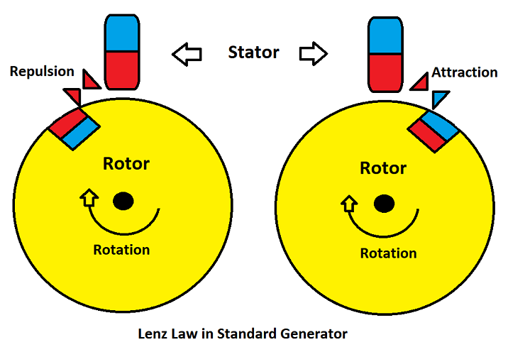
The Lenz Law and Magnetic Drag
As in the above post when current is drawn from a standard rotating generator secondary the exact Lenz Law associated with the Figuera device secondary is at play here. With the rotating generator when current is drawn from the secondary a second field is formed and it is this field that causes the generator motor to bog down. As you can see in the below graph as the coil comes into register or approaches the stator it is repulsed as in N><N. As the rotor leaves the stator it is attracted back to the stator N<S. The reason for this is the Lenz Law which is a second field created within the secondary opposing the change of magnetic field (magnetic drag). This repulsion and attraction, magnetic Drag, of the rotor to the stator is the reason a standard rotating generator bog down when power is draw from it. It take 150% power to get 90 plus % out just from this repulsion and attraction bogging down of the motor, how stupid is this? It takes massive power to overcome this Lenz Law field in rotation and why rotating generators will never be OU. If not for the Lenz Law it would be though because it feeds it self and outputs more power then it take to excite the primary NS field.
Take the above scenario and multiply it by 10 or 20 coils and the results are massive reverse torque place on the rotor that opposes rotation causing the motor to bog down when current is drawn.
  Now with the Figuera stationary generator power is thus drawn from the secondary, the Lenz Law field still forms but in this scenario Figuera uses the Lenz Law to his advantage to induce motion into the secondary. Primaries polarize the secondary with current flow through the secondary and the load an opposing magnetic field will form in the secondary (Lenz Law) just like in a standard rotating generator. Except this time Figuera used the Primaries opposing field to push the secondary (Lenz Law) field across the electric field created by both primaries. According to Physics no opposing magnetic fields will ever join as one field so they remain opposing at all times yet this is not true for the electric fields created by the primaries. They combine as one field (Superimpose)(Superposition) in the same direction. This is why the secondary switches polarity on each end because the electric fields change direction. This my friends is how AC is created in a stationary generator using the Lenz Law field to ones advantage ie NO magnetic Drag . Also it is quite easily to change the current flow very efficiently through the primaries set N and S with the active inductor controller and why in the patent he used a small motor just to rotate the brush. The commutator was positioned on the shaft to turn the AC into DC feeding the secondary feed back into the system. Regards, Marathonman |
|
|
|
Post by Marathonman on Jan 29, 2023 16:09:10 GMT -6
Self-inductance, Part G
The effect of Faraday’s law of induction of a device on itself, also exists. When, for example, current through a coil is increased, the magnetic field and flux also increase, inducing a counter emf, as required by Lenz’s law. Conversely, if the current is decreased, an emf is induced that opposes the decrease. Most devices have a fixed geometry, and so the change in flux is due entirely to the change in current ΔI through the device. The induced emf is related to the physical geometry of the device and the rate of change of current. Understand what I just said, "Most devices and circuits in modern day time have a fixed geometry" that only allow a change in current to change inductance. No where on this planet does it say current is the only way to change the amount of inductance. According to Faraday's laws of induction all that has to take place to create an EMF is a flux change. A flux change can be made in a few ways other than a change in current flow which is the only way taught in our Government controlled education and Corporate controlled higher learning facilities. Using the guidelines set forth by Faraday himself in 1831 all that needs to take place is a change in flux whether it be an increase or a decrease. Since the upper statement deals only with a fixed geometry it is basically only one side of the truth. With the Figuera device, specifically the active inductor controller, we have NO fixed geometry device as both sides are in constant change of increase and decrease in loop count or length if you will. Given a constant current yet a change in loop count within the time constant of the circuit, an EMF will in fact be produced which according to the Lenz Law will oppose the original current flow. If we change the amount of self inductance of the circuit we are changing the amount of opposition to the original current flow therefore increasing the loop count increases the self inductance thus lowering the overall current through the circuit. The opposite of this is decreasing the loop count which decreases the opposition to the current flow thus increasing the current flow through the circuit. Therefore with the increase and decrease in currant flow we just gave DC frequency and as such now falls under inductive reactance which we should all know can control current flow.
Yes!, the active inductor controller blocks the AC frequency component from passing yet allows the DC current to flow with an increase and decrease. This allows the DC electromagnets to perform at their fullest yet allowing the current flow through them to be controlled in the most efficient way possible in this planet. The reactive component of the Figuera device will be close to ZERO losses while controlling current flow with the low wire resistive component being the only losses in the active inductor controller. There will be some core losses but that will be very, very low also especially if laminated core is used. Since there is no reversal of the current flow like that of AC, the core losses will be extremely low as all we are doing is increasing and decreasing current flow.
 As with any inductor, increase the loop count increases the opposition to the original current flow keeping "I" static or fixed. All that changed was the loop count thus increasing self inductance, increasing the opposition, reducing the current flow.
EDIT: Inductance, Self Inductance, Inductive Reactance takes place any such time there is an increase or decrease in current flow. Increasing and decreasing DC gives it frequency just the same as AC and as such falls under Inductive Reactance controlling current flow.
Another cool aspect of the active inductor controller is the storing and releasing of the magnetic potential into the system which offset the opposite side of the system storing into the magnetic field thus equalizing the voltage drop thus allowing the secondary feed back into the system to achieve amplification to the rising electromagnets. And YES!, the Figuera device violates not one Physics law in the process. Regards, Marathonman
|
|
|
|
Post by Marathonman on Feb 10, 2023 20:09:48 GMT -6
Energy obeys superposition in electromagnetism
The energy density at any given point in space is the sum of electric and magnetic energy density. The local space volume doesn't know and doesn't care how those fields got there, whether they are generated by little capacitor and coils or by superposition of a group of opposing electromagnets is completely irrelevant. The only thing that one can measure at any given point are two vectors and the sum of their squares is the energy density. Can that density be raised......YES!
By placing the two identical electromagnets face to face leads to raising the overall energy density by a substantial margin through compression. By compressing the field lines raises the energy density to that of a standard high intensity north/south field. Then increasing one and reducing the other while maintaining field compression aligns the vector potentials of the electric field which equal the square of both electromagnets field potential. The higher the compression the higher the squared energy density.
What is not apparent is the combining of the opposing magnetic fields is impossible considering the fact that they are in opposition and will remain as such throughout the increase and decrease. The electric field are another story which can and will be additive with the special switching of the Figuera electromagnets which align the superposition fields to act as one whole field. The energy density will be the square of the two energy densities.
The only way I can explain it is the two electric superposition vector potentials are in phase in the Figuera device through the unique switching.
Regards,
Marathonman
|
|
|
|
Post by Marathonman on Feb 20, 2023 19:15:02 GMT -6
Physics Facts on the Primaries and Part G
So as I have seemingly throwing out facts concerning the Figuera device. my whole purpose was to get the reader accustomed to realizing there is more then meets the eye concerning our universe and what we were selfishly taught in schools and universities. They blatantly hid certain facts concerning electromagnetism from the macro to the micro. If you honestly think this suppression is not real then there is no reason what so ever you should be on this site. Also if you deny the fact that perpetual motion is possible knowing our earth as well as the universe is in constant motion for billions of years then again you need not be on this site.
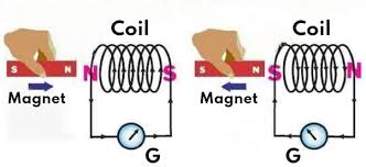
It is a known fact that if you have two Coils like below and you approach the coil the Lenz law states the induced will be in the direction to oppose the inducing magnetic field as is the one on the left. The one on the right shows the same magnet being pulled from the coil inducing in the opposite direct visually confirmed by the deflection needle. These two actions are just the same as if an electromagnet was raised and lowered in current which causes the magnetic field to increase and decrease all in accordance with Faraday's Laws of induction and the Lenz law.
The reason for the reversal of current is because of the fact that when the magnet is being pushed in the front side of the magnetic spin is making contact with the coil wire first. When the magnet is being pulled away it is making contact with the back side of the spin first causing a reversal of current flow. This again is confirmed by the deflection of the needle.
Why on earth do people not think that taking the two electromagnets and face them together with the secondary in between that it would not act the same. If you increase one electromagnet it is still in accordance with all physics laws as the above graph. If you decrease one electromagnet it is still in accordance with all physics laws as the above graph. Just because you increase and decrease a set of opposing electromagnets that they would not follow the same physics laws set forth by Faraday and Lenz.
Taking the set of opposing electromagnets gives the same output as the graph above. The only difference is now you have two magnetic fields and two electric fields that are opposing. According to the graph above, that follows all known physics laws, all that is required to align the electric fields is increase one and decrease the other. By doing so causes the electric fields (Induced) to flow in the same direction. The magnetic field will never combine as one because they are opposing at all times but in this process the electric and magnetic lines are highly compressed raising the over all induced EMF.
It is a known fact that if you have two opposing electromagnets producing say 5 lbs pressure the overall pressure between them is up to 10 lbs pressure. Will the two opposing magnetic fields ever join as one field, Absolutely no under any circumstances. But that doesn't mean the electric field can not be joined with the special switching of the active inductor controller.
Increasing one electromagnet and reducing the other aligns the electric fields and can "NOT" be denied by anyone as it is in complete accordance with all known physics laws set forth by Faraday and Lenz themselves.
Another physics fact is if you wind the inductor the way I have suggested, (need to make a video to prove to people) that the induced on part G will in fact have two opposing fields at the positive brush that will separate the inductor in two allowing the inductor to control two feeds separately yet in complete unison. This is a physics fact and can not be denied. Test this out yourself at home just as I did to prove the Figuera device is in fact an active inductor controller that stores and releases potential to and from the system.

It is a physics fact that in the above scenario that the right side of this winding will be influenced by the top part of the magnetic spin causing a north field at the brush. On the left side the winding will be influenced by the bottom side of the spin causing again a north field at the positive brush. This is all in accordance with physics laws passed down from Faraday himself. If there is any people that has a problem with any of these physics facts then I suggest you dig up Faraday himself and bitch at him. 
The entire 1908 device Figuera built is in exact accordance with Faraday's laws set forth in physics in 1831 and I am dying for someone to prove me, "NO" Faraday and Figuera wrong! 
Regards, Marathonman
|
|
|
|
Post by Marathonman on Feb 21, 2023 14:38:17 GMT -6
Simple Test to Verify
Here is a simple test "ANYONE" can do at their home to verify the inductor winding to achieve a N-N at the brush allowing you to separate the inductor in two thus controlling two feeds separately yet in complete unison. In the Graph below even though it is crude yet gets the point across showing how to wind part G.
In the middle the positive power supply is attached, which is basically the rotating positive brush and at the bottom the negative is attached. Power up your electromagnet and take a pole tester to verify just what I have been saying. The tester will show a north field for both windings and a south at the ends where the windings start.
The reason for the gap on the middle is to easily identify the N-N fields of each side only. If you notice the winding is wound the same way across and the gap will not be there when you wind your real active inductor controller. It will of course be one continuous wind with no gaps.
Starting from the left you are to wind CCW over the top looking at the face, the other end being received from under the bottom. OR the opposite winding from the right starting from under to over winding CCW while looking at the face ending at the left over the top. Either way you will get a North-North at the middle which represents the rotating positive brush.
Of course the core will be a closed core because it will preserve the magnetic fields within. An open core can NOT be used as there is massive magnetic flux losses and your core will be so huge which is impractical, bulky and expensive. Wind the windings right next to each other because this device uses flux linking to increase inductive reactance.
Please remember this is a rotating active inductor controller which rotates at 3000 RPM for other countries and 3600 RPM for the US. Please take cautions as this thing could hurt you so build it well and solid. If what you gathered from my research that the Figuera device part G is one continuous wind, then you would be correct. It is one continuous wound active inductor controller separated by an active rotating positive brush with set N and set S attached to the ends.
Regards, Marathonman
|
|
|
|
Post by Marathonman on Feb 25, 2023 14:55:17 GMT -6
FIELD LINE COMPRESSION AND CORE RATIOS
So you have decided to take the plunge and start building the Figuera device. After assembling your primaries and secondaries and test them you are frustrated that your secondary is not putting darn near nothing out. You then realize that Marathonman may be right with the cores of a 1 to 1 ratio will not work in the Figuera device. Upon further study you find that the field line compression is almost non existent because you did not listen to physics backed reasoning. The below graphs are the reason you are not getting a thing out of your secondaries and why some are screaming this device doesn't work. I hate to be the barer of bad news that YOU are the reason your primaries are not putting a thing out because you chose a 1 to 1 ratio cores.
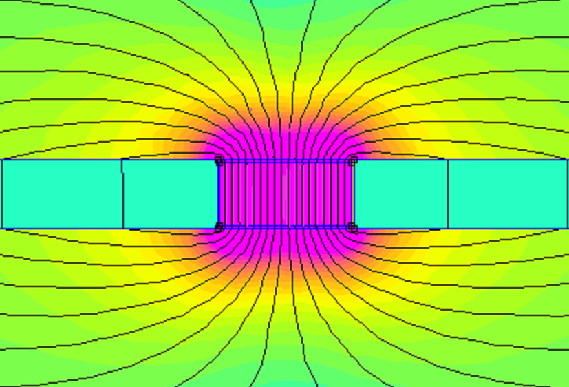
The cores HAVE to be a 2 to 1 at a bare minimum because of the compression of the field lines throughout the sweeping action. Even though the drawing in the patent says it is just a drawing for the comprehension of the device, the drawing of the cores 2 to 1 ratio has substantial merit.
The compression of the field lines is basically like the drawing. The spring in one hand is not compressed with the field lines being farther apart represented by the spring loop gap on the left. On the right the spring or field line compression if you will, is being compressed and the field lines are tightly packed together which allows the output to be substantially higher then non compressed.
Now with the Figuera device with the core ratios being 1 to 1 the magnetic fields cannot reach the other side of the secondary let alone maintain the field line compression between them. To sweep the entire length of the secondary from gap to gap the reducing electromagnet has to be reduced so much that the field line pressure to maintain the secondary output is completely lost. The graph below illustrates this very thing.
The whole reason of the compression and sweep is to sweep the entire secondary from gap to gap. Anything short of that sweep reduces your secondary output substantially because not only is the field line compression lost but the sweep is reduced substantially also. Even if the opposite opposing primary is reduce completely or even shut off it still can not attain a full sweep and field line compression is totally lost.
Now observe the 2 to 1 ratio below, notice how much farther the magnetic field projects past the secondary. This ratio allows not only the reducing primary to get the proper sweep across the secondary but also maintains the proper field line compression through the entire sweep when reduced.
As I have been saying for years, a 1 to 1 ratio core con NOT be used in the Figuera device. It has to be a 2 to 1 ratio or above to properly maintain the proper field line projection and compression through the sweep.
Test this at your home like I did. Take a pole tester and measure any large magnet you have at the house. Or you can make an electromagnet yourself and connect a power supply to it. The pole tester will only detect a magnetic field from the end of the electromagnet or magnet the actual length of the core it self. I tested 1 inch magnets and the field was one inch out. Same thing with 2 inch powerful magnets, it projected a field out 2 inches past it's core. The same with a 6 inch electromagnet with a thousand winds, it projected out only 6 inches past the end of the core. This is called The square of the distance in physics and is quite applicable.
Compressing the field lines of the two opposing electromagnets allows this device to match the high intensity north south field of a standard rotating generator if not beyond.
Your cores need to be like below at a 2 to 1 ratio with the primaries wound with multiple parallel winding small wire specifically wound as electromagnets and the secondary wound according to present day teaching.
Now with the proper compression the primaries can now be reduced yet maintain field line compression throughout the entire sweep.
If you notice the secondary circumference is larger than the primaries to take advantage of the bulging magnetic fields in the process of being compressed. Use this to your advantage as your output will be larger. Remember the output needed by your secondary is split between your primaries so each primary is accountable for half the flux needed for your secondary output.
As you see above the field lines are highly compressed with a high intensity field bulging out so primaries are 2 to 1 ratio minimum with secondaries larger to take advantage of the bulging field.
Regards, Marathonman
|
|
|
|
Post by Marathonman on Mar 3, 2023 9:43:36 GMT -6
Static VS Active
Most if not all schools, Universities and trade schools around the world especially in the US teach the fundamentals of EMF generation that something has to be blown up or exploded to create power. While very hilarious indeed this is not the only way to create power. Other aspects about electronics is completely one sided also as in the static inductor. Again all education facilities teach the static role model of an inductor which in turn require a change in current flow to change flux within the inductor it self. It is impossible for a static device to change it's flux other than from a change in current flow.
While this is 100 % true for a static device or system it is not a complete and lacks a more in-depth review of the device. Can an inductor be made active in a system just like a capacitor, absolutely it can. Just because the static quo school system you were indoctrinated in taught you an inductor is static only does not mean it can be made an active part in the system.
This is exactly what Clemente Figuera did in his device was make a static part an active element in the system by varying the loop count of the inductor with a rotating brush. Just because "YOU" were taught that if current I in the coil changes, the magnetic flux in the coil changes , proportionally to the current, which mind you is a static system model, doesn't mean it can't be made active. The reverse is very true that if Magnetic flux in the coil changes, the current I in the coil changes with respect to time. These two are universally exchanged but just because you were not taught this doesn't mean it is not true.
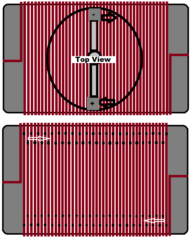
Top Inductor is for Mechanical rotating brush and the bottom is for electronic switching.
Yes!, the roles are universal and Clemente Figuera proved this with his active inductor controller that a change in flux can and will change the flow of current. According to Faraday in 1831 all that is needed to create an EMF is a flux change and according to the lenz law because it was made within the system it will oppose the original current flow. Changing the loop count changes the inductance which changes the current flow. Since Figuera was creative he gave a extra spin on the device by winding the inductor one continuous wind with two ends with an active moving positive brush. This allowed him to control two feeds completely separate yet in complete unison.
Forum member followed my advice on building active inductor controller Part G, imagine that!
So you see an active inductor controller does work and just because you think it can not, well maybe, just maybe, you might want to step back and reevaluate your education on induction and the static device you were taught about.
My grandfather told me once as a kid, "You learn until the day you die" Thank you grandpa for those wonderful words of wisdom. Remember almost every invention ever made started in someone garage that literally changed the world.
Regards, Marathonman
|
|
|
|
Post by Marathonman on Mar 21, 2023 23:13:38 GMT -6
Soft Coupling and Secondary induced Current Flow
As you can see from my graph abiding by the Lenz Law The increasing electromagnet will induce an opposing north field in the secondary. The reducing electromagnet will induce an attracting south field in the secondary at the same time. One is doing the shoving (Opposing) while the other is soft coupled as it is reducing (Attracting) pulling the Lenz Law field across the electric field created by both electromagnets. Current flow will then be from the reducing electromagnet to the increasing electromagnet in the secondary. This will of course be the opposite when when they switch positions and the polarity of the secondary switches poles every half turn of the active inductor controller.
This is how the secondary switches poles while the primary electromagnets always stay opposing at all times. The Positive of the secondary will always be towards the increasing electromagnet and the negative always be towards the reducing electromagnet. This means power is generated on the reduction cycle of the electromagnet. The rising electromagnet is there to keep field line compression and shove the secondary Lenz Law field across the electric field generated and this sequence produces EMF in the secondary in a stationary device.
Remember you are not spinning a huge hunk of Iron so the Lenz Law is not an issue. You are increasing and decreasing the current flow only with a flick of a brush. Your moving the massless, weightless fields from side to side over the secondary while maintaining field line compression between them. There is no physical movement except for the bloch wall or collision point of the two fields being shifted back and forth over the secondary.
Regards, Marathonman
|
|
|
|
Post by Marathonman on Mar 28, 2023 20:50:58 GMT -6
Please do not think the graph above uses small magnets or electromagnets to induce the secondary. It is just my graph to illustrate to you just what is taking place in the generating part of this device. These electromagnets have to be at least 2 to 1 ratio and specifically would as electromagnets with the highest flux as possible. Matching the North and south high intensity field of a standard generator will take many, many winds. Even if you decide to make it small like two inch primaries and one inch secondaries it still has to be would accordingly. Plus do not wind as one single wind as that will have to much self inductance and inner winding capacitance being to slow to keep up with the controller changes. Use multiple windings in parallel to get the highest flux possible.
Anything else is just a waste of time.
Regards, Marathonman
|
|