|
|
Post by bigeasy on Aug 21, 2022 4:31:10 GMT -6
Hello
Since Figuera's patent was rediscovered in 2003, I have read a lot of posts on several forums to learn and understand how Figuera's device works.
1question: marathon runner do you know of the existence of an EXCEL or other spreadsheet to determine the various construction parameters of the Figuera device.
2 question: I could not find on the WEB anyone who built, operated and got more output energy than input energy with operating readings, i.e. OVERUNITY , can -be that people have solved and use their device for themselves but do not communicate anything !!!!!!!!!!!
Do you know these people?
Thanks
I do not have sufficient theoretical knowledge to carry out research and develop the calculations necessary for the construction of the FIGUERA device.
|
|
|
|
Post by Marathonman on Aug 21, 2022 18:40:49 GMT -6
No!, I know of no one that has excel sheet. Yes!, there was one whom taught me a lot and that was the original replicator whom had way to much knowledge of this device for me not to believe him. Everything he shared with me I verified and was true.
Common knowledge tells me as does the four patents this device works as did eyes witnesses in Barcelona Spain that stated his house lights, a twenty horse power motor and the streetlights in front of his house were lit by this device. The patent office said so!.
|
|
|
|
Post by bigeasy on Aug 22, 2022 2:11:01 GMT -6
your quote in one of your messages :
part G is a magnetic resistance device rarely used in today's modern world, a forgotten relic in a world of silicon ic's that can be had in any style, shape or form. part G is unique as it splits one DC feed into two separate independent feeds. this feat is accomplished through two opposing fields as the currant enters part G through it's winding's causing two opposing north magnetic fields. these two magnetic fields restrict the amount of saturation of the core restricting currant flow and through self inductance or rather dynamic self inductance (magnetics).
Hello
There is a word that I do not understand in your various messages:
you use the word "currant". According to the readings for me it would rather be the word "current" with an e and not an a.
when I translate: "currant" in French it gives a red currant fruit.
Maybe the two spellings currant and current are used for the same meaning to you if that's the case disregard my remark.
|
|
|
|
Post by Admin on Aug 22, 2022 22:28:07 GMT -6
No you are correct, it was a miss spell it should be current of the two feeds as current flows from negative to positive through the windings on part G's core to the positive brush causing two opposing north fields that split the inductor in two halves allowing the control of both in unison.
Regards,
Marathonman
|
|
|
|
Post by bigeasy on Aug 23, 2022 7:10:01 GMT -6
Hello I recovered an ELECTRIC MOTOR ARMATURE to build part G of the FIGUERA device. The dimensions: outer diameter 125mm 5" internal diameter 63mm 2.5" Height 75mm 3" 24 notches Weight 4 kg 8.8 lbs Can you estimate the power of this core for the G function? What power in Watt will it give to build the Figuera generator? ![]() 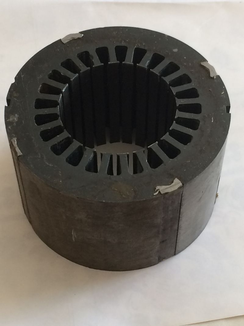 |
|
|
|
Post by Marathonman on Aug 23, 2022 7:29:30 GMT -6
Well first off that is a hard question because i do not know specifics of core from manufacture but you can estimate from other like cores or other motors like this.
Another thing is Figuera did not have a round core . The patent was drawing and worded showing only the brush travel and not the rest of the core. At that time the only company capable of doing such precision work was Ziess who at the time made Variac control with an EI core. This allowed him one continuous wind with the ends connected to set N and to Set S while the brush rotated. He used a fat center E I core in his original.
Using a toroid will be very difficult to balance as did the original replicator did. he stated it was a bitch to balance. But yet it can be done. Also remember you are building the Active inductor controller that controls the electromagnets. It is the electromagnets that produce the power through shifting of the collision point.
EDIT;
The part G is the central point of all the three sources of potential to power the primary exciting side of the device and is as follows, The reducing set of electromagnets, The reducing side of part G and the secondary feed back into the system. These three sources of potential are what power the device after the initial start up that feed the electromagnets controlling the current through them as well. The potential will rise far above the starting 100 volts to say 140 to 160 volts thus suppressing the starting potential. If you read through the tech thread I have posted all the specs on what part G actually does in the system.
Regards,
Marathonman
|
|
|
|
Post by Marathonman on Aug 26, 2022 9:21:36 GMT -6
Here is the main problem, 98% of the world population has NO clue as to how a standard generator even works.
Like a standard generator there is an exciting side and a power generating side. The exciting side consists of the primaries and the AVR. The secondary and the load is a complete separate system and had no drain on the primary side of the system with no other connection except for a small secondary feed back to the exciting side. Once the primary side is up to running condition the primaries no longer act as a load to the system except for the ohmic losses and the exciting side potential is thus circulated throughout the exciting side circuit to maintaining the pressure which maintains the magnetic field.
Figuera's device does just that, the primaries and part G (ACTING AVR) are the exciting side and the secondary and the load are the power output side. These are complete separate systems just like a standard generator. One rotates and the other does not so the one that doesn't rotate has to have power to start it. As standard generator rotates it produces power to feed it self.
In the Figuera device once it is up to running conditions the secondary feed back replaces losses to the exciting side and give rise to amplification to the rising primaries. This amplification is the replacement of pressure associated with the reduction of the reducing primary and the loss of pressure. Adding it back to the rising primaries assures the opposing pressure between the primaries is maintained at all times thus the output remains steady.
These are two complete separate systems. The exciting side induces the secondary side with no direct coupling thus the draw on the primaries is non existent unlike a standard transformer that are directly coupled thus a substantial draw on the primaries and the AC feeding it. To may people think a generator acts like a transformer and couldn't be farther from the truth. They are two different beasts completely. You can use transformer equations to build a generator but they act and are completely different. It is this association that kills people in replication.
Since the primaries of the Figuera device are opposing there is no hard coupling and this can easily be swept from side to side with just a slight change in current which is what the active inductor controller is for.
Here lies the problem, all the replicators do not understand a standard generator so how in hell do they think they can build the Figuera device especially when they don't understand that either. Knowing the exact function of a standard generator really helps with the Figuera device. In a standard generator you have the Lenz Law to attend with. When power is drawn from the secondaries a second field is formed according to the Lenz Law and this field will oppose the original influencing field. This is called the cogging effect in a generator.
When a rotor electromagnet rotated up to a Stator it will oppose the field because you are drawing power off of it and will have an opposing field associated with it. This opposing field causes massive reverse torque place upon the rotor opposing the rotation. When the rotor leaves the stator in it's rotation the field will reverse polarity and attract back to the rotor thus opposing it's rotation causing massive reverse torque again on the rotor. This is the reason why generators are so inefficient and take 150% power to get 98% back. it take massive power to overcome the Lenz Law opposition. When you plug a power tool into a portable generator and pull the switch the generator will bog down then recover slightly yet still noticeably labored. This my friends is the cogging effect otherwise known as the Lenz Law.
If not for this cogging effect a standard generator will in fact be OU because it self sustains. Yet we have the Lenz Law killing this OU at every rotation. So how on earth do we rid the generator of this cogging effect. You do what FIguera did with opposing electromagnets then use Lenz's Law to your advantage and sweep it back and forth over the secondary coil with opposing fields. Each opposing electromagnet pushes this opposing Lenz Law field to the other side of the secondary coil only to reverse then get shove back to the other side by the other opposing electromagnet. So as you can read FIguera side stepped the Lenz law and used it to his advantage. He now can sweep the fields from side to side with a flick of a rotating brush on an active inductor controller.
Please read what i have written on the controller in the Tech thread, Part G is truly amazing when you know what it does in the system.
Regards,
Marathonman
|
|
|
|
Post by Marathonman on Aug 26, 2022 16:49:37 GMT -6
I almost forgot, Do you realize all Generators use Rectified DC through their field coils to produce the strongest field possible then rotate the secondary through those fields. DC is far superior in making a magnetic field then that of AC. This is why the Figuera device uses DC in his device excitation yet uses self inductance of the expansion and retraction of the circuit to give DC, AC like qualities thus able to control current flow with inductive reactance.
Regards, Marathonman
|
|
carlo
New Member

Posts: 18
|
Post by carlo on Sept 4, 2022 14:04:34 GMT -6
good evening to all builders of the figuera generator opp replicators like. and a long time that I do not post on the site but never interrupted the search on the device. o built part g and are already in the third generation of primary as i taught you marathon runner. and I must say that either I found a good output at the output but still not at the output like my brother and we often exchange opinions and drawings.
I can't post photos on the site. however my research goes on at the counter.
greetings to all manufacturers on 09/04/2022 carlo italia
|
|
|
|
Post by bigeasy on Sept 6, 2022 13:04:56 GMT -6
good evening to all builders of the figuera generator opp replicators like. and a long time that I do not post on the site but never interrupted the search on the device. o built part g and are already in the third generation of primary as i taught you marathon runner. and I must say that either I found a good output at the output but still not at the output like my brother and we often exchange opinions and drawings. I can't post photos on the site. however my research goes on at the counter. greetings to all manufacturers on 09/04/2022 carlo italia Hello Carl It's a shame not to share your experience, I am at the beginning of the construction I am looking for information to allow me to calculate the different functions of the Figuera device. can you describe the construction of the primary and secondary coils and the "G" induction drive, how did you size them? |
|
carlo
New Member
Posts: 18
|
Post by carlo on Sept 6, 2022 13:41:23 GMT -6
hello great easy good evening
here I am not able to perform calculations x the coils or toroid x part G also x first bench tests or used recycled wire from transformer and recovered coils a 4/5 kw variac that my brother had recovered from old plants.
I am still testing the primary connected as on the figuera device but in ac with the self-built secondaries. I think that they are still at the first experiences and I don't think it is the correct way.
The rotating manifold is built with brass plates mounted horizontally on a bakelite board 20 cm x 20cm are about 19
and glued with transparent epoxy resin connected to part g on the end with threaded hole and cable lug. rotating brush of mm30 x 25mm adjustable in rotation diameter to increase or decrease the contacts.
the slats are 1mm apart.
part g I had a toroidal transformation of dm 20 cm internal hole 10mm
thickness 5mm weight about 6 kg wound with mm2. 9 wire about 130 turns with output every 4 turns inductance 60 mh
premarie nr 2 total 4 coils. primary coil 212 turns wound with 4 coils of 53 turns dm wire mm2
I am testing everything but I think I will need to buy more wire to make at least 2 other primaries
greetings to all co-leaders
Charles
|
|
|
|
Post by Marathonman on Sept 6, 2022 15:40:22 GMT -6
Hello fellow Figuera builder,
The entire Reason this site is here is to share resources on the Figuera device. I have spent years studying and shared my findings yet others have not been so kind. It seems as soon as they start to see ou they bail and get greedy. this is the basic reason for me not continuing my research. I have spent a lot of my own money and a little from donations a long time a go. Either the builders thought it should be another way or just plain didn't understand it in the first place.
The device should be calculated as follows.
!. decide your output...... say hypothetically 5,000 watts.
2 Secondary core designed to put out 5,000 watts divided by how ever secondaries you want ie say 7 primaries so 5,000 divided by 7 = 715 watts each plus head room.
3. Primaries designed to be able to handle half the load of the secondary so each primary needs to handle 358 watts plus headroom so say 400 watts or more remembering the gaps between them and need to be no less then 2 to 1 length.
4. Part G needs to be calculated as the potential needed to power both sets of primaries at one high and one low plus motor and headroom of a few 100 watts.
even if the magnetic field released from the primaries and half of part G is a little high or low the secondary feedback will compensate for this. Once the device is started with 100 volts the internal voltage of the device will climb to 140 to 160 or more suppressing the starting supply and will run indefinitely.
5. The secondaries can be LARGER IN CIRCUMFRENCE then the primaries to take advantage of the bulging magnetic fields being compressed to match that of a high intensity field of a standard generator. This is common sense and I have posted graphs to support this claim and is Physically sound.
Regards,
Marathonman
|
|
|
|
Post by Marathonman on Sept 7, 2022 9:33:28 GMT -6
Also remember this device can NOT operate without a load present on the secondary. No load means no current flow and opposing field formed in the secondary to be pushed from side to side by the opposing primaries.
Regards,
Marathonman
|
|
|
|
Post by Marathonman on Sept 12, 2022 10:18:33 GMT -6
   The top pic is sectional windings as this will allow the Figuera device electromagnets to respond instantly to all current changes as part G makes them. If you wind the primaries in one long winding the primaries will have to much self inductances and will be to slow to respond to current changes. Sectional winding is harder to implement yet reacts lightning fast to changes in current flow. Remember the two to one ratio or larger. The second pic is the use of a larger secondary to take advantage of the bulging magnetic and electric fields. I have posted a graph from a major magnet manufacture on this very subject and according to physics it is very sound to take advantage of all the field available to the secondary. Remember the one to two ratio or larger. The third pic is from the actual magnet manufacture showing the actual fields bulging in opposing fashion. You can easily see the intense compressed fields bulge out so please design your secondary's to take advantage of this high intensity electric field. These are not just some of the wall suggestions but backed by sound experiments and real world physics as are the opposing electromagnets. The reason they are not N and S electromagnets is because a north and a south will always combine to form one magnetic field. You can NOT vary an N and S field without them combining as one field, period!. Also with the standard generator you have the rotation which then is plagued by the Lenz Law of attraction and repulsion of the rotor and stator. In the Figuera device being opposing this Lenz Law is not sidestepped but used to his advantage in the sweeping action of the secondary's using this secondary Lenz Law field shoving it side to side over the secondary's. Regards, Marathonman |
|
|
|
Post by Marathonman on Sept 13, 2022 9:11:33 GMT -6
Hello I recovered an ELECTRIC MOTOR ARMATURE to build part G of the FIGUERA device. The dimensions: outer diameter 125mm 5" internal diameter 63mm 2.5" Height 75mm 3" 24 notches Weight 4 kg 8.8 lbs Can you estimate the power of this core for the G function? What power in Watt will it give to build the Figuera generator? ![]() I would personally not use that core because of the inside Fins. The slots where the wire goes is hollow and that reduces the magnetic field considerably. It would cause you to almost double you loop count. Regards, Marathonman |
|


