|
|
Post by Marathonman on Oct 17, 2019 11:36:59 GMT -6
Pressure Requirements
I had posted this before but i had added the lbs pressure on the side in yellow. It is just to get you to realize the pressures involved in your goal of output. The final pressures can then be split between the amount of inducers you care to work with or a pressure you feel comfortable in working with. Always remember the amount of induction presented to the secondary for your specific output is split between two inducers. Both inducers will equal one inducer at full power all the time yet is split between the two of them which part G shifts the total current to either of them to get the sweeping action.  Marathonman |
|
|
|
Post by Marathonman on Oct 17, 2019 12:08:52 GMT -6
The Patent Drawing is Misleading You
I also would like to post an image of the Figuera part G, "R" and commutator bars as is portrayed in the patent. I have already posted my information on the existence of commutator and "R" so this is a continuation of that. In the first pic as you can see it is the patent portrayal of part G which is stated specifically as "Just a drawing or in it's elementary manor to facilitate the understanding of the operation of the device". it is in no way the higher form of the device which is an active inductor.
 As you can see the device as pictured shows little scribble lines that connect part G to "R" which is just to show that part G has some " Resistance associated with it". Inductive reactance would be hard to show resistance between the wires so Figuera used a fictitious "R" to portray resistance in it's elementary manor. Again i will repeat that last statement in a question to the readers. How on earth do you suppose Figuera could have represented inductive reactance in any other way then the form he chose. The most logical way would be a separate graph that represents resistance which is the way he so chose. He then even specifically explained in the patent that it is shown drawn in it's elementary manor to facilitate the comprehension of the device. The next pic is the part G active inductor in a smaller form just for educating people of the reality of what part G actually is. It has a rotating roller brush just as the original did. It will control current perfectly as the brush rotates each connection 180 degrees from each other in complete unison.  Below is a modified version just to illustrate the point that Figuera used "R" just to show there is some resistance within the system and that it actually resides within the wire not some separate entity as most people think on first impression. Figuera also concentrated all his attention to just the ring distributor or the actual brush travel, he totally ignored the rest of the core which is illustrated below with outer part of the core removed.  As you can see this depiction is exactly like Figuera's patent drawing showing that part G has some resistance which is in it's elementary form to understand that part G has some resistance associated with it. In reality part G's resistance is inductive reactance which is formed from the looping of the wire around the core with a changing positive brush contact. Also when Figuera is describing semi-circles he is describing part G in two halves, ie.. The upper semi-circle and the lower semi-circle which if you study the picture you will see that the two halves are actually the same loop of wire around the actual closed core. I hope what i have posted will enlighten people to the reality that "R" and commutator bars in the Figuera device just simply do not exist and are nothing more then a rotating brush on a closed core inductor being split into two halves with opposing magnetic fields. If anyone has any such questions just ask as there has been to much confusion with the Figuera patents that are totally needless. The sooner you realize "R" does not exist thus resides within the wire looped on the core the sooner you will be on the road to a correctly working part G. The other builders presently on this site are doing a wonderful job with their interpretations and just in need of a little tweaking to get to where they need to go. Regards, Marathonman |
|
|
|
Post by Marathonman on Oct 21, 2019 14:34:48 GMT -6
One Wire or Two.....or Three.... Or four.
I would like to bring something to the table that just might of been overlooked by people. When winding your primaries and using the series parallel winding technique, when i refer to parallel winding, it doesn't necessarily have to be completely separate winding. Using one wire winding with several taps at each layer or other areas will attain the same thing as separate winding's. Winding with this technique will allow the coil to be powered with a lower voltage yet match the field of the higher voltage one length coil. There are many ways to wire them and a person needs to realize that all the present day formulas state N number of ampere turns yet NEVER states anywhere it has to be one wire, it simply states N number of ampere turns. So please keep this in mind when winding your primaries along with the fact that the overall field presented to the secondary is split between two primaries with the current shifted between them to attain the sweeping action.Both combined always add to 14.8 lbs per kilowatt shifted side to side irregardless of their position on the secondary. Part G simply shifts the total current, more to one, less to the other and vise verse very efficiently. Regards, Marathonman |
|
|
|
Post by Marathonman on Oct 23, 2019 19:09:13 GMT -6
EDIT or ADDITION to;
When referring to the patent, specifically part G and "R" It was automatically assumed by most everyone that all the lines connecting the two together actually exist at all or all at the same time. this unfortunately is not the case. The lines are of course a representation of the positions of the brush connection that move current a little more or a little less to either set N or set S coils. This is why Figuera drew the lines so small and faint yet damn near everyone assumed they really existed in reality.
Granted it would of been better if Figuera drew all of them them with dotted lines not just between the commutator bars yet he did not which of course it was his patent. They are just the representation of the brush position on the ring distributor to visually show that each position represents more or less inductive reactance (resistance), which i might add would be literally impossible to illustrate. I myself would have no idea how to visually illustrate inductive reactance other then what Figuera chose to do in 1902 - 1908.
It amazes me still to this day that people selectively chose what facts to acknowledge and what facts to blatantly ignore, very much so on EF and OU. That is why the FIguera threads are totally dead because those lame brains ground them into obscurity. (how unfortunate) What amazes me even more is the fact that 99% of people, especially University educated, have absolutely no clue as to the possibilities of inductive reactance in an active device or position in a circuit. Just the thought of using the magnetic flux to current ratio to control current flow is so beyond their grasp that very few actually get it on their own. Even then years of me posting right in their faces some still refuse to acknowledge that this device not only controls current in the worlds most efficient manor, yet actually does what it says it does being a stationary generator.
Just because the replicator has failed or one so chooses to ignore the facts of this device does not change the facts that Figuera had many working device that transitioned up to the 1908 version of a completely stationary generator. Choosing to ignore these fact or refusing to do the research to validate doesn't change the fact that we live in a perpetual machine that has spun for millions of years before us and millions of years after we are gone.
You of course can choose to ignore facts, i personally choose to embrace them with open arms which is why i am here to spread this information.
take it or leave it.
Regards,
Marathonman
|
|
|
|
Post by Marathonman on Oct 24, 2019 11:14:09 GMT -6
Who Owns This Energy Quanta Anyways?
A very good site to study DC, associated circuits and it's effects are **** ibiblio link.**** you can go to the index page and download the whole series as a PDF for study at your own leisure. DO THIS NOW it helps. What i really like about the site is Tony R. Kuphaldt adds some de-complexity to his discussions and answers. He also asks for public feed back (open source) to correct inaccuracies through out his publication. Another thing i love about his work is he is not afraid to post the correct way current is flowing unlike sorry, misguided main street Science and Physics that is content to deceive the public for 100 plus years and counting. One of the interesting facts about his site is it inadvertently exposes the inaccuracies of the polarity shift of a coil or inductor when the field collapses, well at least to me it does even though he posted a polarity change sign. Since the current is flowing from negative to positive to start with, then the field collapses releasing it's kinetic energy in the very same direction as to maintain the present current flow it is physically impossible for a polarity shift to occur. If the potential is flowing in the same direction as the original flow why on earth would you think it will change polarity. I think there is a pressure change not a polarity change that gives us the illusion of a polarity change or action there of a different spin direction but that is not possible. As per sparky Sweet the current supply through the coil is one energy quanta yet when the kinetic energy is stored in the magnetic field it then becomes a separate energy quanta which then belongs to the coils as it was created within the coil it's self. Since it now belongs to the coil, when released, it will then travel through the circuit as being high pressure traveling to the other side of the coil as to even out the pressure. There is no positive and negative anywhere in our Universe, it is all about high and low Eather pressure modalities and electricity follows this to the letter. Electric systems of man are in fact Eather pressure systems that require a finite time to rise to a working pressure. This just happens to be very fast to us since it travels up to 300,000 miles per second not the lowly 186,000 postulated by the banker plagiarist puppet Einstein that halted the entire Physics and Science advancement, ON PURPOSE ! Try this test at home to verify for yourself. take a variac as a power supply through a bridge rectifier with some smoothing caps or what ever variable power supply you have that is able to vary the voltage & current flow. Run it though your primaries at a good power then reduce the voltage and or current flow. While the current is being reduced take a pole tester to the end of the electromagnet and tell me what happens. Did the polarity change by reducing the current flow? hell no it did not, all it did was release the stored kinetic energy into the system to try to maintain the previous current flow in the same exact direction of the original current flow that created it. The polarities did in fact NOT CHANGE. this is the same for an inductor in a boost converter as the polarity does not ever change. This is just one of many sad, inaccurate cover up postings of main street Science and Physics that truly does NOT fully understand electricity or a magnetic field for that matter that has boggled many a minds needlessly halting the advancement of humanity. This list is as long as the world is wide so we as humans not Corporate or Government thug need to correct these within OUR RANKS. I am sure they really know the truth, yet refuse to let the average person know the real information and not allowing it in main stream school books. On closing, If a polarity change took place it would then be impossible to have opposing electromagnets stay opposing as each time you reduced they would then shift polarity. Just something to think about in your Figuera Journey when wiring up your system for self running. Inductors and electromagnets will always release it's stored kinetic energy that will and must travel to the opposite side of the coil that created it so this is of course your clue to correct wiring loop of the device. Ask your self how can the potential build up pressure in the exciting side of the system and maintain it all while still adding potential from the secondary feedback without interruptions. Keep in mind that opposing fields in part G will rectify the same and that coils then take ownership of the newly created energy quanta. If it was created within the exciting system from an external source it will then remain in the exciting system to build up the correct pressure needed. EDIT; PS. If current or potential from the secondaries is feed into/through part G, it will then store the kinetic energy in the form of a magnetic field. That stored potential is NO longer part of that original potential or energy quanta. So even though the secondary may be feeding part G, once it enters the inductor stored potential it is no longer part of that feedback potential and thus circulates within the exciting system and stays there. Potential NOT used by part G returns to the secondary in it's circulating fashion passing right on by as if part G was a straight piece of wire. Potential is still there, just not being used just like the primaries i have discussed Think of this as a fuel pump like in your car. the unused fuel not used, which under pressure is recirculated back to the gas tank. Only a small portion of the actual fuel running through the lines is used by the motor, the rest just circulates throughout the system. The same thing is happening with the Figuera device, only a small portion is actually being used, needed or excepted by part G the inductor as IT controls the current flow. if the magnetic field is at full potential, as in max stored potential per the amount of current, it will just pass right on by. Regards, Marathonman |
|
|
|
Post by Marathonman on Oct 27, 2019 10:45:57 GMT -6
BEMF or CEMF
I just realized there needs to be some clarification of different actions or reaction taking place in part G and other devices. Main street science seems to think these two below are or seem to be so insignificant that less than one page of discussion is devoted to them anywhere on the net. The following is "MY" overall assumption of the two and "MY" assessment of the obvious distinct differences between them. BEMF; Is the reverse voltage potential created from the magnetic linking of the wire loops within part G's circuit. With an increase and decrease of magnetic flux to current ratio it creates a voltage that opposes the original flow. It is the same as reluctance yet given a different name with the exact same results, it is still BEMF. This is also the same as a motor that produces a reverse generated voltage in it's coils that oppose the original current flow. With a motor that has 12 volts of potential used in it's operation as it turns it will then get hit with 9 volts BEMF the next rotation of that coil which reduces the efficiency of that motor. To increase that efficiency you have to remove that BEMF before the coil is recharged as an electromagnet to increase the efficiency of that motor. Look up UFOP on Youtube for this very interesting material. both actions produce a BEMF that will oppose the original current flow. CEMF; Is the release of stored kinetic energy from the magnetic fields. When released it does not travel the opposite direction as some think confusing it with the above scenario, It travels the same direction which it was traveling when it was stored. This is the direct distinction of the two that gets constantly confused with each other fore which main street science is very good at doing. CEMF is just stored potential getting released that does not oppose the original current flow, It aides the original current flow by increasing the voltage which aides and allows the possibility more current to flow than the original would have allowed. it increases the voltage in the system. I hope you can now see the difference between them as one is EMF created in the reverse direction and the other is just released stored kinetic energy. They can also happen at the same time as is being utilized in the Figuera part G as BEMF or inductive reactance is opposing the original current flow and CEMF is being released from the magnetic field into the system aiding or increasing the exciting potential to the rising electromagnet. EDIT;
upon further review it would be wrong to go against the present day information of CEMF. Counter electromotive force is what it is, a counter force to the original flow of potential so it would seem like BEMF and CEMF are essentially the same thing. We are still left with the facts as a released potential does in fact travel in the same direction it was traveling in when it was stored into the magnetic field. Since the spin direction is in the same direction it will therefore travel in the same direction.
Here lies the problem, what the heck do you call stored potential being released into the system? ? if there is a name for it, i sure can not find it. maybe it should be called FREMF as it really is Forward Released Electromotive Force or RKEMF Released Kinetic Electromotive Force. ? if there is a name for it, i sure can not find it. maybe it should be called FREMF as it really is Forward Released Electromotive Force or RKEMF Released Kinetic Electromotive Force.Regards, Marathonman |
|
|
|
Post by Marathonman on Oct 30, 2019 7:14:35 GMT -6
Lenz is your Friend!
As you can see from the previous post the Lenz Law is very prominent in the Figuera device. yes, this is NOT a Lenz free device like some seem to insist. Without The Lenz law hard at work this device would cease to function. Figuera's device works with the Lenz law and uses it to his advantage unlike many so called free energy devices that seem to struggle to avoid it. He was and still is a genius for using the Lenz law to his advantage.  MM |
|
|
|
Post by Marathonman on Nov 1, 2019 18:13:32 GMT -6
Inductive Reactance Review
Just a quick review of how and why inductive reactance is present in the Figuera device part G even though it is DC operated. As you all should know by now ac opposing potential is called inductive reactance to not confuse it with plain inductance which is essence it is just in the reverse that opposes the change which caused it, created with the circuit it's self. Since the Figuera device is DC operated because DC is much more efficient at powering an electromagnet then that of ac, a much stronger field can be had and utilized from the electromagnets. Figuera in his infinite genius using DC, used a change in the position of the positive brush contact to literally change the winding count on each side of the brush. Since it was within the time constant of the circuit you are adding or subtracting inductance to that side which is the magnetic flux to current ratio and in doing so causes a rise and fall of current flow. See graph below on how inductive reactance with a positive brush movement will cause a current change. 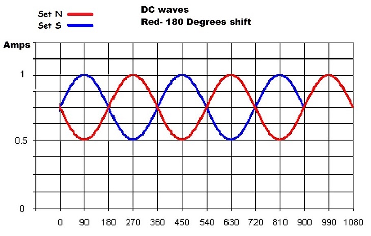 With the change in inductance taking place we have a reverse emf generated within the circuit it's self that opposes the original flow. With the current rising and falling we then have just given DC frequency which now falls under the realm of inductive reactance. A DC current flow with inductive reactance initiated by inductance with the end results of a current change and frequency addition. This has been independently verified by a Physics graduate from a major university to be true that inductance can and will control current flow in the Figuera part G active inductor. 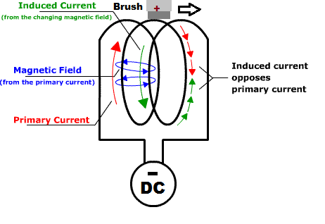 The more winding's we add to that side of the circuit the more reduction of current flow we have and vise verse, the less winding's the less opposition to current flow. As long as we have a continuous movement of the brush the inductive reactance will continue to increase and decrease as will the current flow of both feeds. Since we are using DC in this device, any such time we stop the brush movement the inductance will subside and the current flow will return to full unabated level minus the ohm resistance of the wire. The added benefit of utilizing DC in an ac like fashion is the always positive feed that NEVER reverses. The electromagnets are always kept at a high magnetic point producing what they were designed to function as and that was specifically an electromagnet to produce the highest magnetic and electric field possible only reducing to get the sweeping action across the secondary which in turn induces movement into the secondary. All while maintaining a stationary position. EDIT;Just so you know, an Inductor is the most efficient way to control current on the planet. Much, much more efficient than that of a resistor or resistance. regards, Marathonman |
|
|
|
Post by Marathonman on Nov 3, 2019 14:19:41 GMT -6
Exactly how the secondaries create an EMF in completely stationary system
Just the other day i was discussing the Figuera device to someone i have met being a Vet also. The point came up of confusion of just exactly how the secondaries create an EMF being a completely stationary system. If this person being of rather good intelligence has some confusion, then just maybe others have or are in a similar situation. All generators utilize a Motional Electric Field situation of generated EMF. The difference between the transformer should be quite obvious as a transformer deals with an expanding and contracting magnetic and electric fields only to produce an output of either higher voltage with lower current, even one to one or a lower voltage with higher current. A transformer is a transformation NOT a generation of potential. this is a big difference between each other and should be noted and remembered as such. Not so with a generator that literally either rotated the secondary through the magnetic field or rotates the magnetic field it's self to produce a motional electric field. either way both generate a motional electric field and as such needs motion of some sort. In the Figuera device the reducing electromagnet is creating the electric field yet it is a stationary electric field that would require a secondary to be moved through the field in order to create EMF just like a standard generator. Since this generating system is completely stationary, some type of movement has to occur in order to produce a motional electric field to generate an EMF. In order to create movement in the secondary you not only have to polarize the secondary but it also has to have motion of some type across this field thus must be pushed from side to side across this newly created electric field to create an EMF. Again motion of some type has to occur. The exact moment current begins to flow in the secondary and the load, a second field, according to the Lenz Law, will form in the secondary. With the secondary opposing field between the two opposing primaries it is easily swept from side to side by the rising primary across the newly created electric field by the reducing primary. This action will create a motional EMF in the secondary, even though this motion is virtual motion, it is motion just the same to the electric field and according to Faraday an EMF will be created just the same. Each primary are accountable for half the pressures required for the secondary output yet each one is totally oblivious as to the presence of the other primary electromagnet being opposing and having an opposing secondary field between them. Each primary reacts as if they are almost in saturation and reacts as if it was a single unit unaware that it is an integral part of a system reacting in complete harmony. Each primary is either filling up the secondary with flux or emptying it's flux without any knowledge of the other primaries presence being opposing let alone having the opposing secondary field between them. So the final outcome of this symphony in complete harmony is the opposing primaries compress the magnetic field lines to match that of a standard generator, then are reduced and increased at the same time to not only create an electric field but to also shove the opposing secondary field from side to side creating the illusion of secondary motion to this newly created stationary electric field. I again stress, it behooves you to ask questions if you do not understand the information provided thus the reason to become a member so one can ask question to aide in the understanding and or replication of this device. As you already know or should know, i freely open source my amassed knowledge of information (More than any other sites combined) to the public in order give the the average citizen a chance at gaining additional freedom from the dictator ship of Government and Corporate domination of our lives. Even if you decide to not become member, you can still help in becoming a backing member to help bring this badly need technology forward and make it available to every single person on this planet irregardless of race, creed, color, sex, geographic location or financial status. This is my dream for humanity, i hope it can also be yours. Regards, Marathonman |
|
|
|
Post by Marathonman on Nov 5, 2019 17:17:40 GMT -6
Recap
So i think we need to do a slight recap what we have learned so far about the Figuera device just to refresh your mind or for others that have a problem reading everything skipping to the end. *The primaries are opposing in nature as to compress the magnetic field lines to match the high intensity N/S field of a standard generator. They are opposing for a reason and that is to avoid direct linking as with a transformer. This is to ensure the primaries excitation potential is not taxed and or drained which would require a constant uninterrupted supply feed like a transformer does. There is no direct linking in the Figuera device and that is why it can self sustain. *The primaries are longer then that of the secondary ( 2 to 1) to project a proper field to be compressed to the proper field strength with both primaries accountable for half the needed flux presented to the secondary. Always remember the square of the distance. Test for proper lbs pressure before they are put into testing or production scenario. *The primaries need to have parallel winding's to reduce resistance, self inductance, which will increase the speed of response to the slightest change in current flow in a timely manor and to maintain proper field line pressure. Be sure to wind them specifically as electromagnets as they do not control the current flow, that is the job of part G. The current flow throughout the device is controlled by part G inductor controller not any other piece in this device. *Keep everything adjustable especially the primaries as to balance out the magnetic fields. Make the primaries exact copies of one another to ease the balancing stage of adjustment. * Keep in mind that the primaries must be able to sustain half the magnetic flux of the secondary and to attain the needed pressures at the length of the secondary. *The secondaries can be larger diameter then that of the primaries (core and coil) as to take advantage of the bulging compressed fields of the primaries. Wind them according to present day teachings the same as a standard generator output winding's. *Part G is an Active Inductor that is wound one layer on a closed core to preserve the exiting potential which uses a rotating positive brush and opposing fields to separate the inductor in two halves. Each half utilizes the magnetic flux to current ratio as to either increase or decrease the winding's which changes the inductance of that side of the controller. Either increase or decrease in self inductance changes the current flow of that feed which then gives current frequency which then falls under the realm of Inductive Reactance. *Inductive Reactance initiated by inductance that causes a current change thus the addition of frequency. DC given frequency to act like ac just not ac. *Part G's inductance will be calculated on the amount of reduction that it needed for your primaries to achieve a full sweep across the secondary. This is dependent on core material used, amount of magnetic flux achieved, core ratios ect... *Part G becomes the power supply once the starting is removed so plan accordingly. Must be able to handle all lower sums added together plus some headroom. This includes all electronics used to switch it if using electronics. EDIT;Just remember Part G controls the current through the device and must have just enough inductance from it's winding's to get the sweeping action of the primaries to just clear the secondary core and no more.. Not enough and the output will be low, to much and the output will be low. Once the sweet spot is found you will know immediately as the output will rise substantially past the starting voltage. The primaries must be able sustain field line pressure at the length of the secondary when the other primary is reducing. Remember the magnetic field line pressure is maintained through out the entire sweep of the secondary so make sure they can attain the pressure needed to do so. Part G is there to manipulate the current flow more to one than the other and vise verse. It efficiently shifts the current to either of the two electromagnets without converting it into heat as does a resistor or resistance which is non recoverable. In this scenario it conserves the exciting potential in the form of a magnetic field either storing or releasing that potential at the proper time. Regards, Marathonman |
|
|
|
Post by Marathonman on Nov 15, 2019 10:58:10 GMT -6
It's Faraday's Fault! Flux Did It!
What some people are failing to realize is the secondaries can care less how the flux is changed as long as it is changing thus according to Farday's Laws of Induction will produce an EMF. The last time i checked the only requirement is a change in flux but i guess Physics must be different for them and them only. This fact will take place irregardless if you disagree or whine and cry it can't happen, it will still take place. To bad it is Faraday's Laws of induction not yours and Physics is the same throughout the entire universe like it or not. In the standard generator you have a NS field and an SN field for which the secondary is moved through. The exact same poles are used in both cases with the only thing that has changed is the direction of the flux travel. Using both poles causes a very highly intense field between the two poles fore which i am sure you know or should know. In the Figuera device the exact same thing is taking place except the generation device is stationary and as such some type of movement has to take place and the increase and decrease of the primaries fulfill this requirement that increases and decreases the magnetic flux across the induced circuit. Again the same thing is taking place yet in order to get the same intensity as a standard generator you have to place another electromagnet opposite of the first to compress the field lines to match that of the standard generators high intensity filed. Once that is accomplished you then have all the requirements to produce an ongoing AC EMF like that of the previous standard method. Again the secondary can care less how the change takes place as long as it does. So with two of the exact built north faced primaries place to oppose each other will in fact have magnetic flux in opposite directions, one right to left, the other left to right which is EXACTLY like a standard generator which has one field one direction and the other, the opposite direction. Again the Figuera device has fulfilled the same requirements as the standard generator with fluxes in two different direction and an increase and or decrease to produce an electric field. The only thing left is to move the secondary coil through each oppositely directed magnetic field like that of the standard generator for which Figuera used the secondary opposing Lenz Law field produced from the original current flow. It is then shoved from side to side by the rising opposing primary field that fulfills this requirement of movement to produce an EMF according to Faraday. Each time the primaries transition from increasing phase to decreasing phase, the opposite primary shoves the opposing field of the secondary across the newly created electric field from the reducing primary. Thus the two oppositely directed flux paths, in two different direction, being in exact accordance of a standard generator, will in fact create an AC EMF in exact accordance with Faradays laws of induction. Each oppositely directed magnetic fluxes occupies the secondary one at a time thus is the standard pattern base requirement for the production of AC. So as you see the Figuera device is an exact mimic of a standard generators mode of EMF generation which is in accordance with Faraday's Laws of induction and as such, violates not one single Physics laws that has been brought forth on this earth. Since we are no longer rotating a massive hunk of iron through the oppositely directed magnetic fields, we no longer have to deal with the massive reverse torque placed upon the rotor which can now be replaced by a very small motor to rotate a group of brushes on an active inductor that is used to control the current flow through the electromagnets. We now have the ability to take a small portion of the output to feed and maintain the induced pressure required to maintain our output indefinitely. The Figuera device uses the exact same three coil pattern base for the production of EMF as does all generators since the days of Praxii in France and as such CAN NOT BE DENIED OR IGNORED by anyone on this planet. Regards, Marathonman |
|
|
|
Post by Marathonman on Nov 17, 2019 12:12:36 GMT -6
ARE YOU FREE LOADING?
Re-emphasis as to why the Figuera device can be self sustaining. According to M.I.T graduate Sparky Sweet, once the field of an electromagnet is established the draw on the power supply is reduced to just the ohmic resistance of the wire. Since the kinetic energy is stored in the magnetic field it can not store any more magnetism as per the amount of current flow (pressure) so the current just passes right on by as if it was a straight piece of wire.  As the pic above shows the opposing fields of the primaries once established actually require very little to maintain since they are no longer a substantial load on the power supply and in reality become a separate energy quanta from the original current that created it. Once part G and the primary electromagnetic fields are established they then require very little to maintain. the only requirement is the residual pressure in the inducer side of the system has to be maintained in order to maintain the magnetic fields in the primaries and part G. Once the system is in operation a very small replacement of potential supplied by the secondary feed back into part G is utilized in order to maintain it's operation. Since it is an actual generator, it performs this replacement over time as does a standard generator. As the pic above shows the opposing fields of the primaries once established actually require very little to maintain since they are no longer a substantial load on the power supply and in reality become a separate energy quanta from the original current that created it. Once part G and the primary electromagnetic fields are established they then require very little to maintain. the only requirement is the residual pressure in the inducer side of the system has to be maintained in order to maintain the magnetic fields in the primaries and part G. Once the system is in operation a very small replacement of potential supplied by the secondary feed back into part G is utilized in order to maintain it's operation. Since it is an actual generator, it performs this replacement over time as does a standard generator.
What is taking place is the inducer side of the system, which consists of part G and the two sets of electromagnets (inducers), magnetic fields are established then varied in intensity in order to get the sweeping action of the primaries. Figuera is using two opposing magnetic fields (two inducers in tandem) to act upon another magnetic field (induced) all while not depleting the inducer side of the system. This non depletion is accomplished by not magnetically coupling the primaries to each other or the secondary like that of a transformer which taxes the supply as additional load. Since this coupling never takes place the reducing primary can quite easily create an electric filed and the increasing primary can quite easily shove the opposing secondary field across this electric field with no magnetic coupling what so ever. So what we end up with is two fully formed electromagnetic fields which are then slightly increased or decreased to induce another electromagnetic field which is coupled to a load so the current is then circulated in a closed system as is the inducer side of the system. With both being closed systems the current is quite easily manipulated with the storing and releasing of potential from part G the active inductor controller. Once the device is operational with the proper pressure present in the inducer side, part G uses inductive reactance to steer the current flow to the inducers in an increase and decrease fashion, which i might add requires so very little effort that a small motor to rotate the brushes is all that is required in order to function properly. In the long run the Figuera device uses the exact same principals as that of a standard generator except the fact that he eliminated the rotation of a huge mass of iron with winding's that causes the reverse torque which requires an additional massive amount of power to do so. I personally would rather choose a device that once started will run almost indefinitely as opposed to a gas guzzling, air ,water and soil polluting device that is literally killing us and the earth we live on. Not to mention making some sorry sick Corporation filthy rich in the process while we the people suffer so dearly. Regards, Marathonman |
|
|
|
Post by Marathonman on Nov 17, 2019 16:32:43 GMT -6
Questions to Ask Yourself!
Lets try a different approach to the Figuera device. Let me ask the readers a few questions that when answered will give you a better understanding of your own abilities towards the Figuera device, hopefully. these questions are the very question the ney sayers need to start asking before slinging false accusation and inaccurate information left and right. 1. Knowing the standard generator uses a high intensity field which has a north and south end to increase intensity, how else could you get the magnetic lines of force to compress to increase the output or intensity without linking like that of the two fields of the generator or that of a transformer.? 2. Would it not be logical to assume that two opposing fields compress the magnetic lines of force under pressure.? 3. Knowing two identical magnetic fields when placed in an opposing fashion, will they not have fields in opposite direction and will the secondary exposed to each one separately not fulfill the requirements of AC generation.? 4. Once the opposing fields are established at full capacity just like that of a standard generator, how will you induce motion into the secondary or at least appear to have motion in it knowing it takes motion of some sort to create EMF.? 5. According to the Lenz Law, when current begins to flow in a secondary coil, will it not produce a secondary field that opposes what created it in the first place.? 6. As with the above question in mind, would it not be concluded that if a load is not attached to the secondary the Lenz Law field will not form.? 7. From your experience on this earth, does it not take effort to move something of mass knowing mass is generally involves some sort of weight and the larger the mass the more weight involved.? 8. With the opposing Lenz Law field of the secondary positioned between the two opposing magnetic fields of the primaries, would it not seem to you that it would require very, very little effort to move the massless, weightless fields from side to side as compared to the huge mass of iron in a standard generator.? 9. With a inductor using DC or AC, does not the inductance depend on the amount of winding’s on that inductor.? 10. Is not the inductance produced within the circuit it’s self the consequences of the Lenz Law.? 11. Knowing an inductor’s inductance is calculated per the winding’s, would it not be easily concluded that more winding’s represent more inductance which according to the Lenz Law is the opposition to the original current flow.? 12. So with the above statement would it not seem logical to conclude that that if I add more winding’s to the circuit while current is flowing would it not change the current flow on a steady basis.? 13. With the above statements in mind, would it not be logical to conclude that with a steady rise and fall of current flow that the DC flow is given frequency.? 14. Since inductive reactance happens with the rise and fall of current flow in AC yet DC in the Figuera device has just been given a rise and fall of current with frequency, would it not be logical to assume that inductive reactance is what is controlling current flow in the Figuera device.? 15. Knowing an inductor stores and releases potential in the form of a magnetic field, would it not be a logical choice and a smart idea to use that extra potential available to your advantage in the system instead of wasting it through the burning off of potential through heat like that of a resistor which is non recoverable.? 16. As with the previous post above, would it not be logical to assume that if the draw on the electromagnets are reduced to just the ohmic losses once the magnetic fields are established, that it would then be very easy to move the fields in a sweeping action yet maintain those established field with little to no effort or expenditure of potential.? 17. Would it then not be a logical conclusion to all these question combined that such a device can then be self sustaining.? The very answers to these question through your own research are the questions that need to be asked and answered if one is to not only understand the Figuera device but replicate it in it’s entirety. EDIT;
Let my ask this you this final question in which i will answer for you, how do you think 12 volt lift magnets can attain up to 11,000 lbs lift from such an extremely low voltage.?
A; from the use of shorter parallel winding's which allows a higher voltage per turn then that of a one wire length.Regards, Marathonman |
|
|
|
Post by Marathonman on Nov 21, 2019 22:03:41 GMT -6
I think one of the overall problems is how people are viewing part G. sure part G does all those fancy things i have posted in other posts which i think it was written quite clearly, people need to also realize or start thinking in terms of an amplifier.
Part G is the central collection or mixing point of all the stored and released potential so it should be quite obvious that it will amplify the source potential. When the reducing primaries and the reducing half of part G are combined, will react the same as two series batteries and as we should all know series will increase the voltage which is the combination of both potentials. These combined with the secondary feed back will have a substantial increase in potential which can then be regarded as am amplifier of the original signal or potential as it is many times higher then the original.
Also, as i have said before, raise the voltage, raise the current flow, which is exactly what Figuera did in his device to forward bias the rising primary to compensate the reduction of field line pressure of the reducing primary. This of course is done for a few reasons i have also previously explained as no movement, no motional electric field production.
So it is quite simple, part G is not only multi talented with many facets to it's operation yet quite elegantly is an amplifier of potential at the same time. For that very reason of why the polarities or parts of the device can not and will not operate correctly if rearranged.
Regards,
Marathonman
|
|
|
|
Post by Marathonman on Nov 25, 2019 11:37:47 GMT -6
Part G!, Your So Special.
On continuation of the previous post the discussion of the secondary feed back into part G and my reasons for my stand on why part G becomes the power supply when starting is removed. The reason part G becomes the power supply when the starting is removed is the released potential of the primaries and the reducing half of part G get added to increase the voltage of the system along with the secondary feed back to attain amplification. There has to be some way of a power supply to regulate the current flowing through the device or self destruction is inevitable. The opposing magnetic fields within part G help not only control current flow through the two feeds separately yet regulate the saturation of part G's core at the same time which in turn regulate just how much potential can be stored in the magnetic field. If the core is near saturation then the magnetic field will no longer except further secondary potential so the current will pass through to circulate in the secondary system unused or conserved if you will. Once the pressure is built up in the system to running conditions it can be easily maintained by part G Inductor Controller. If the system is rearranged some how or changed then these properties of part G, the system and or device can not take place and thus not self regulate of self run. This is how the system self regulates is through the opposing magnetic fields in part G which regulate the saturation of the core. If the core is full or near saturation then the secondary feed back will pass right on by as if it were a straight piece of wire because the saturated core will not allow more storage into the magnetic field. The saturation in turn will regulate how much potential feeding the primaries which dictate the secondary output thus the return feed back into part G. If the saturation and or field is low them the partial current from the secondary feed back will then be excepted and or stored within part G. As you can see the operation of part G is similar to a mag amp saturation control yet much, much more refined and specific in it's functions. This is why the attempt in replication can not and will not function without part G nor be to large or to small. If part G is to small the core can not supply the load (primaries) way to large and the self regulation is thrown out of wack. Regards, Marathonman |
|


 ? if there is a name for it, i sure can not find it. maybe it should be called FREMF as it really is Forward Released Electromotive Force or RKEMF Released Kinetic Electromotive Force.