|
|
Post by creasysee on Aug 28, 2019 13:22:59 GMT -6
This thread is using Electronics to switch part G not by them selves. the Figuera device will not work without part G as it is the inductance that controls current flow. 2018 Oct 7 I'm started to build an electronic version of the device:  The core ID 63mm, OD 127mm, Height 93mm. Used from variac 1.8kW (220V 9A) and core already has 276 turns of wire 1mm (AWG18). 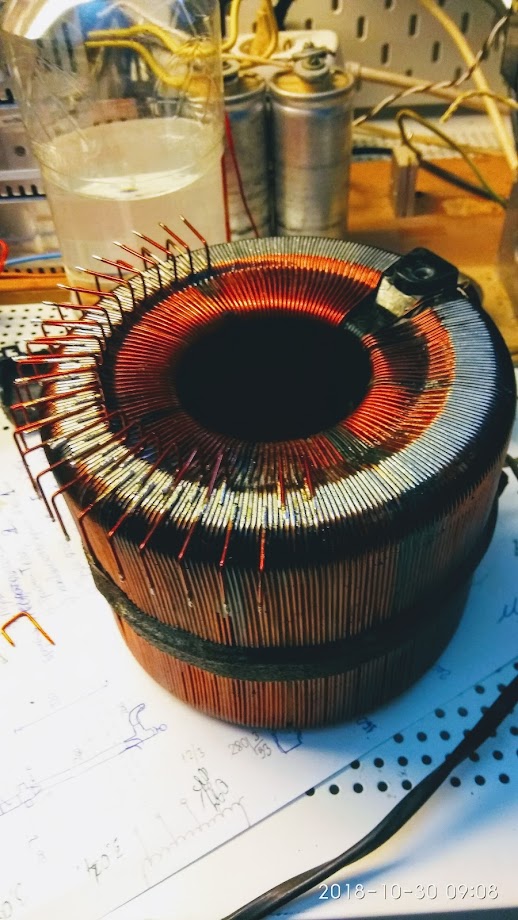 The sliding surface of the variac winding is tinned and leads are soldered. Initially, approx 276 keys were planned, for each turn of the winding. After estimating the cost and labor, the number of keys was reduced to 92, - one a key by 3 turns. For 46 keys, leads are made up, for the other 46 leads down. Now the keys are soldered only to bends upwards, i.e. one key for 6 turns.   Keys are soldered with drivers TC4420, strapping scheme and LED for control. I regretted when installing LEDs - they eat a lot of energy. CMOS сontroller output may not give so much.   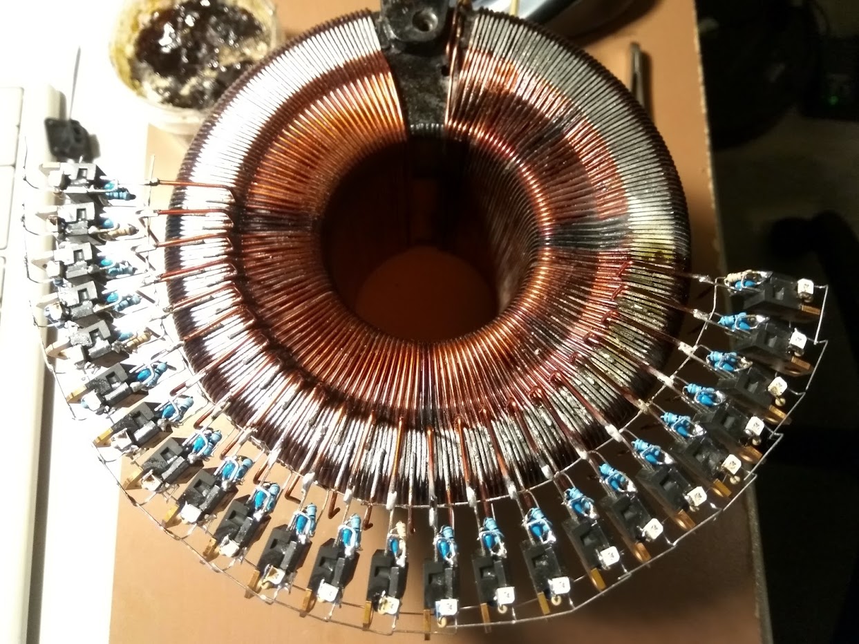  It's the scheme of the controller that manages driver keys. It consists of two independent bi-directional shift registers, connected by outputs using a logical element OR. This is necessary to overlap the control pulses in time so that BEMF doesn't occur when the key is closing. The pulse sequence in the second register is identical to the first but shifted in time for overlap. 92 keys. The period is 20 ms, the pulse duration is 108.5 μs (for support a full period, we should first go to one side, then to the other using reverse registers). The overlap is planned 3-5 microseconds.    |
|
|
|
Post by Marathonman on Aug 28, 2019 15:19:51 GMT -6
That's what i am talking about. please post the rest of your build and also the rebuild. all electronic build will be here for ease of excess. great job Creasysee.
just remember to use an Inductance meter this time.
MM
|
|
|
|
Post by cornboy on Aug 28, 2019 19:56:52 GMT -6
Hi Creasysee, why are you rewinding your core?.
Regards cornboy.
|
|
|
|
Post by creasysee on Aug 29, 2019 8:22:50 GMT -6
2. having to many winds on part G can also have a detrimental effect on the output. as we all know the Cemf produced within Part G active Inductor (Lenz Law) reduces the original current flow as the brush rotates. If there are to many winds the primaries are reduced to far and the loss of field line pressure will occur between the two primaries. The pressure has to be maintained even when reduced through the entire sweeping process otherwise the output will plummet considerably. There is no reason not to use thick wire which lowers the IR2 losses thus equates to the most efficient Inductor possible. Also, a high inductance gives a high reactance, this gives low current, this gives a low pressure. You can compensate current by increasing voltage (I thought so first), but the wire size is very low here and transistors for high current and high voltage very expensive. |
|
|
|
Post by Marathonman on Aug 29, 2019 8:44:56 GMT -6
That is what i was referring to, to many winds equate to to much Inductive Reactance, to little current flow. as for the transistors, that is why i couldn't pass up the IGBT's at such a good price. they are getting more greedy and designing transistors that handle less current for more money. on Mouser and other places i research and the ones i bought at 400 watt capability being discontinued, the replacements are two to three time more expensive. total Corporate greed.
as you may or may not have read the reducing primary is reduced to JUST clear the secondary then back to full potential. if to far or to short you will just be farting in the wind.
Cornboy;
He is redoing his part G core because he has way to much inductance from the amount of winding's on the core which is reducing current down to far. with the removal of winding and a transistor reduction his part G will be great. an Inductance meter is a must. shooting for 100 volt one amp is a good start.
MM
|
|
|
|
Post by creasysee on Aug 29, 2019 9:15:21 GMT -6
My Part G - DC resistance 3 Ohm. Inductance 3 H. XL = 2*PI*F*L = 2*3.14*50*3 = 942 Ohms @ 50 Hz.
|
|
|
|
Post by Marathonman on Aug 29, 2019 11:06:41 GMT -6
That inductance needs to be according to the amount of actual sweep you need to just clear the secondary then back to full potential. at 942 ohm plus the three DC resistance you will reduce the primaries so much that the pressure between them will fail. i have already given you a graph on the amount of inductance generally needed or around .400H or 400mh. the below ohm calc tool shown just how much amperage you will have if you do not change it. we are not dealing with 12 volt light bulbs any longer we are dealing with keeping the pressure between electromagnets. the little light show of just how Inductive Reactance is over, now it's time to dial it in to be of some actual use for your electromagnets. please observe the calc too and the extremely low current flow your are getting with your present system not including the other three ohms of DC resistance. i have no other clue is to how to get you to understand this flaw in your part G. the first is with 100 volts which is very bad, the second is with 12 volts which is extremely bad. MM   |
|
|
|
Post by Marathonman on Aug 30, 2019 22:21:05 GMT -6
something to consider when searching for transistors. the ON TIME will be 20 ms per revolution which will be divided by the number of taps you have from start to the end back to start. the actual on time of each will be low, adding the ends are on for three times longer so there fore use that on time and the SOA of the transistor to make your decision. and maybe use low power LED's this time.
MM
|
|
|
|
Post by Marathonman on Sept 1, 2019 14:31:21 GMT -6
Electronic Switching. This post explains the whole reason of why the end contacts have to be on for longer time then the ones in the middle. looking at the graph below please observe the brush contact as it rotates around in the ring distributor. notice the time at the bottom contacts in the middle winding's compared to the ends that are connected to Set N and Set S. you can see for yourselves that the ends are one for 3 to 4 times longer then that of the middle. the reasons for this is the induction of the primaries on this long will start to decay causing a primary induction (inducers) roll off in the secondary which is notated in the Sine Wave graph to the lower left. the inductive roll off causes the secondary (induced) roll off as well resulting in a perfect output Sine Wave used by all present household appliances today. if you are attempting to use electronic switching on top of part G's core you must incorporate this switching method in your device or the output will be hard on appliances. since the brush will make contact with two at a time the on time will extended for the middle contacts. this graph is just a point of reference. this is an automatic addition inherent in the mechanical rotating brush. MM  |
|
|
|
Post by Marathonman on Sept 9, 2019 11:07:21 GMT -6
I would like to discus a few fact that the electronic version followers might want to consider in their implementation. when or if you are using high side drivers using an N channel Mosfet or IGBT as i have discussed many times before, that a timing overlap of the channels is a must. since the mechanical version is make before break scenario to reduce sparking and eliminate current interruptions, the electronic version must contain this feature also. if you can get the timing to overlap without a timing overlap cap then this would be the best path to take. either way the timing of leading channel has to be completely on before the lagging channel turns off. if not BEMF will come from part G and this is bad.
now to my point in question is of the Bootstrap capacitor. the Bootstrap cap is used to increase the gate voltage above the collector voltage as so to turn on the transistor when using a N Channel on the high side. if you are using a high side driver then the Bootstrap capacitor has to have enough capacitance to keep the Transistor on for the time period you so desire. my point is if the driver has multiple channels connected to it as does the end connection as they are on for three to four times longer then the Bootstrap capacitor must reflect this also. this means that what ever capacitance is used to on the center overlap channels it must be three to four times the capacitance for the end channels in order to keep the transistor on for the duration of time specified.
these very reasons are why i originally went with a PNP for the high side as it has much less driving circuit complexity.
i hope this makes some sense.
Marathonman
|
|
|
|
Post by creasysee on Sept 10, 2019 6:58:09 GMT -6
 The first module is soldered. Testing was successful, the video shows that the LEDs are lit with overlapping. Overlapping is 200 ms, stepping is 500 ms, it's programmatically set now. The module can control 8 channels. For the test with 24 keys that are soldered to the toroid already, 3 modules are required. The number of modules is not limited, the scheme can be scaled. The testing program for the Arduino Mega 2560 will be provided later. |
|
|
|
Post by creasysee on Sept 10, 2019 7:06:35 GMT -6
The second module is assembled. Scaling is tested. The speed of switching on video is increased by software (step 125 ms and overlap 50 ms). For testing 2 boards in the previous code of the Arduino program, only the upper limit of the cycles changes from 7 to 15. For three boards - to 23. Formula is: k = (8 * n-1). The scheme shows how modules connected:  |
|
|
|
Post by Marathonman on Sept 10, 2019 10:26:46 GMT -6
Thanks for posting the schematics and for the videos.
looks great, fantastic work.
Marathonman
|
|
|
|
Post by creasysee on Sept 16, 2019 9:07:47 GMT -6
Modules connected in series:  The first test for control. Power to the driver and the keys are not yet served. Two power supplies are too big, but I don't have others. First PS + 12V for the Arduino through a 9V DC / DC converter, the second +5V, in total will give + 17V to power the drivers. A power supply will be separate, using a variac. The latest version of the sketch is here: drive.google.com/open?id=1VTHVoQhcSBQyROkUQYKzDZgNoPlGyZhP Regards, creasysee |
|
|
|
Post by creasysee on Oct 7, 2019 10:10:15 GMT -6
The power 12 Volt, 2 bulbs 12 Volt 5 Watt. Frequency 0.5 Hz.
Regards,
creasysee
|
|


