|
|
Post by Marathonman on Nov 29, 2019 16:29:37 GMT -6
In your journey building the electromagnets you must have some way of measuring the amount of pull force your electromagnets can achieve when powered up instead of guessing. Using a variable dc supply and a home made metering device will allow me to do this. What i will be doing is using a modified fish scale anchored on one end and a metal plate on the other this way the electromagnet is attracted to the plate and the digital meter give me the pull force of my electromagnet. With digital display like below or mechanical scale this can be bought on line rather cheaply and a small 1/4" - 1/2" iron inch plate can be found almost anywhere. If using a magnet for the attracting plate, you must test the magnet first then subtract that pull force to the final pull force so i would suggest a plain iron plate. Digital meter will give you an exact force of your electromagnets.  With a set up like this one can quite easily test your electromagnets before rigging them up in the system. This allows you to test out different winding schemes so as to not get disappointed later with no output from lack of proper pressure like most are doing. I strongly suggest testing electromagnet pull force before putting into your test system. With the power supply i have in the works, it will limit the current to three amps and allow me to vary the voltage with the variac from the wall. Remember, your electromagnets are accountable for half the needed flux of the secondary, so if you were to need 14.8 lbs, which is the needed pressure per kilowatt, each electromagnet must hit 7.4 lbs per square inch non saturated. Edit; Remember when winding coils the BS right hand rule is used for the conventional people but the left hand rule is used for the actual current flow from negative to positive.Regards, Marathonman |
|
|
|
Post by Marathonman on Dec 6, 2019 11:05:11 GMT -6
I have to say that the Cores that i have purchased at 750 plus shipping were Quite expensive being .014 M-6 silicon iron lamination from Temple Transformer. The previous pure iron core i had were ridiculously expensive at almost 500 bucks for two sets. At least with the last purchase i have 8 complete sets to work with that will output 10 kilowatts. An alternative is to use old microwave oven transformers and cut them to size. Even the use of old discarded or used transformers is a great way to reduce costs. In the United States there are so many homeless (Thanks Democrats) that it is literally impossible to find discarded transformers and the like anywhere unless you know people at the recycling centers. If a transformer is acquired then hopefully the wire will be intact as wire is also very expensive. In the U.S. the cheapest wire i have found anywhere is EIS Wire. their prices for an 80 lb spool is half the price of others. EIS. EIS link
Sure it is a pain to dismantle transformers but if you do not have the funds to purchase then one must do what it takes to get the job done. Just try to get the primaries exact copies of each other and even go so far as to weigh each primary to get the exact amount of iron in each core. Taking your time on your build and with the winding technique suggested will allow you to achieve almost perfect electromagnets. Read and absorb all information on this site and think about your next move. not sure of something, just ask away ! Regards. Marathonman |
|
|
|
Post by Marathonman on Dec 30, 2019 11:09:05 GMT -6
Reiteration of Primaries
In your attempt to replicate you must take certain factors into consideration when constructing your primaries. It has been shown that the primaries are accountable for half the needed pressure of the secondary output so I will lay out some design criteria to follow or keep in mind in your construction. I will give an example for which to be a guide in your consideration and are a must if you are to succeed in your endeavors. Example; Say you have a goal of 1 kilowatt of secondary output for which the secondary core MUST be able to handle with headroom. At 14.8 lbs per square inch of pressure to output 1 kilowatt the primaries each are accountable for half of that pressure at 7.4 lbs per square inch each. If you are using a 2 to 1 ratio and need to reduce one primary 1/3 rd to get the sweeping action then that primary is reduced in pressure from 7.4 x .33 = 2.44 lbs reduction for a total of 4.96 lbs per square inch pressure. If you add the rising primary pressure to that of the reduced pressure you get 7.4 + 4.96 = 12.36 lbs per square inch which is not enough to maintain the 1 kilowatt output any longer. To get the sweeping action you must reduce one primary while the other is rising so in order to maintain the 1 kilowatt output that reduced pressure must be added to the rising primary. While the reduced potentials from the reducing set and half of part G are used to off set the rising side storing into the magnetic field, the amplification to the rising side is the purpose of the secondary feedback and to replace losses. The secondary feedback gives rise to amplification replacing the reduced pressure of 2.44 lbs to the rising primary increasing it’s pressure to 9.84 lbs per square inch. 9.84 + 4.96 = 14.8 lbs per square inch maintaining the 1 kilowatt output at 14.8 lbs per square inch. Your primaries MUST be constructed to be able to hit this added pressures peak in order to maintain your output. This replacement of potential coincides with the circular brush movement and the rise of the sine wave of the secondary feed back with the end result of a linear pressure increase of the rising primaries. Remember when in testing phase your system without the secondary feedback your total output will be reduced by 1/6 th of the original output of 1 kilowatt so this means the output will be at approximately 833 watts. This is of course just an example and each build will very according to your required output total divided by the number of secondary cores present. The primaries must have the proper winding criteria to meet the demand of needed pressure at the distance of the secondary where the two opposing fields collide. This is achieved by the proper amount of amper turns according to the formulas provided that can be found on line. The formula states “N” number of turns but NO WHERE does it state it has to be one conductor. Paralleled conductors can achieve the “N” number of amper turns while reducing the overall resistance and self inductance of the coil or electromagnet. Using this winding technique you can achieve the goal of specifically would electromagnets with the quickest response time to current fluctuations or changes of part G current flow. This of course does not rule out multiple taps on one conductor so these type of winding techniques will allow a lower voltage source to power strong electromagnets raising the overall voltage per turn. It is highly recommended to test the pull force of your electromagnets before they are put into a total system scenario. Each electromagnet must be EXACT copies of each other in order to simplify the balancing of the system fields. Each field must be of the same intensity in order to achieve balanced fields across the secondary and must be similar in peak flux. Same weight, same dimensions, same length, same winding count with same winding technique. Using these suggestion and techniques will allow you to build the perfect Figuera electromagnets. Regards, Marathonman |
|
|
|
Post by Marathonman on Jan 6, 2020 11:06:07 GMT -6
Compression and bulging fields
The Figuera device has bulging magnetic fields which is a fact of opposing magnetic fields in repulsion. Even though i have not tested this out i am 100% certain that a larger secondary can be used in your build to take advantage of this scenario with no effects on the primaries what so ever. I have posted the bulging magnetic fields graph i downloaded from a reputable magnet reseller that depicts the fields in repulsion and the bulging effects i have described. My approach is if it is there why not use it to add additional output to your device. It is going to be there if you use it or not so use the field to your advantage.  Edit; The bulging effect was verified in later post. Regards, Marathonman |
|
|
|
Post by Marathonman on Jan 8, 2020 10:50:53 GMT -6
Observe the Graph as it explains the lbs pressure throughout the entire sweeping action. If you were to have a 1 kilowatt triplet core the 14.8 lbs PSI is maintained through the entire sweep as the reducing side of the system and the secondary feed back forward biases the rising electromagnet to allow more current to flow increasing the flux output for that rising primaries. 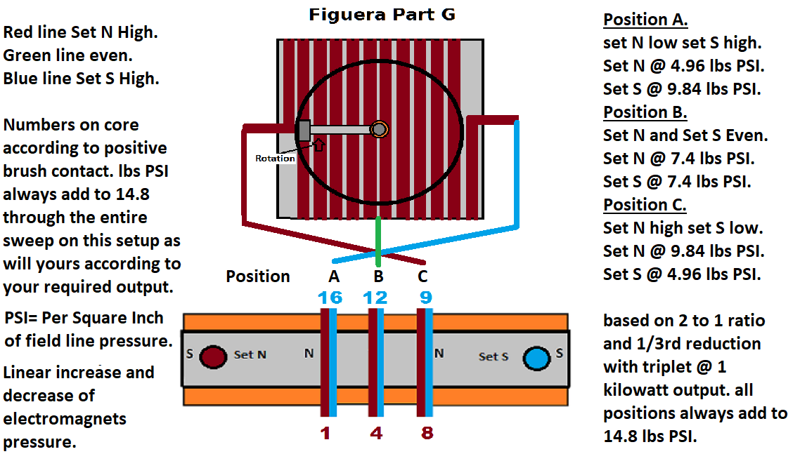 Regards, Marathonman |
|
|
|
Post by Marathonman on Jan 8, 2020 11:21:48 GMT -6
I was reading a good book the last few days from 1910, Solenoids Electromagnets and Electromagnetic Winding's. it basically verified just what i have been saying about multiple parallel winding's on the primaries. for instance it states the time constant for two coils in parallel as opposed to series is only one forth of what they would be if they were connected in series. even though the coils are harder to implement the end results are far superior to that of one long single conductor. it will allow a lesser voltage source to be used with a higher voltage per turn.
Where the electromagnets are connected in series, the total line current passes through all of the winding's, while each winding consumes a portion of the total voltage, whereas, in multiple conductor coil arrangement the total line voltage is across the terminals of each winding, while each winding consumes but a portion of the total current, therefore the multiple conductor arrangement requires or can take a finer wire to wind with.
This style decreases the reaction time (speed) of the electromagnets and reduces resistance which is the efficiency killer of a system through heat production which is non recoverable.
Remember parallel winding's is your friend and one long single conductor is NOT.
Regards,
Marathonman
|
|
|
|
Post by Marathonman on Jan 9, 2020 12:56:30 GMT -6
The information gathered in my investigation of Figuera said there was a motor in the system of 20 hp yet makes no mention of it being used. so as the original replicator and i were discussing at one time that the motor was connected to supply feed back on the secondary to keep the timing in check. It seems that with just a resistive load the secondary timing is off at almost 90 degrees there of and as such will cause the secondary feedback into part G will also be off as well. This phase mismatch will not introduce the proper amount of feedback required of the system at the right time which will not allow the system to self sustain and also the output to suffer dramatic reduction. The graph below shows the primaries and their pi radiun's being 180 degrees out, but also without the proper feedback it shown the offset phase of the secondary with a resistive load only. with the proper feedback from the motor that was installed into Figuera's system allowed the phase of the system to realign the voltage and current as it should be. It may well be corrected with an AC capacitor who knows. 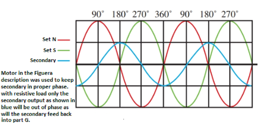 Regards, Marathonman |
|
|
|
Post by Marathonman on Jan 15, 2020 9:41:44 GMT -6
Basically you can look at Part G as an adjustable or variable inductor that changes the amount of inductance each per side as the brush rotates. The brush or brushes according to the patent make direct contact with the winding's which eliminate the use of a commutator with commutator bar set up that everyone is fooled into believing by the patent picture.
Electric generation- Dielectric inertia torque generated using a magnetic field varied with respect to its pressure zones against the dielectric reflector.
This is irregardless of whether you move the coil or move the magnetic field, the outcome is the same.
Regards
Marathonman
|
|
|
|
Post by Marathonman on Jan 22, 2020 10:07:00 GMT -6
20 HP Capacitive timing
Looking at the above post on the graph showing the secondary out of phase or out of timing, it shows the load attached to just a resistive load causing the timing misalignment. With an capacitive load the voltage laggs current by almost 90 degrees which will keep the secondary in phase with the primaries. This pressure of the Capacitive load against the secondary field helps keep the timing right so their always has to be an capacitive load running even if it is not being used. Part G is an inductibe load 90% out and the load motor is Capacitive load 90% out so they balance each other.
Regards
Marathonman |
|
|
|
Post by Marathonman on Jan 23, 2020 12:17:33 GMT -6
The real diagram Figuera should of posted is the one below. it would of made a lot more sense then the resistance box he chose which was nothing but a rats nest of confusion. But then again i think he was planing on giving the 1908 patent to the world as he knew he was dying. **Below pic shows open core which is just for illustration purposes only. Figuera used a closed core to preserve the magnetic flux within part G active inductor controller.**  regards, Marathonman |
|
|
|
Post by Marathonman on Jan 29, 2020 13:51:02 GMT -6
Quotes from Figuera and Buforn;
1. “However, as these variations in intensity of the current flowing through the magnetic field, cause the production of electrical current that can be used for all kinds of purposes, and produced current will be alternating (AC) but a simple commutator will make it continuous, if so you desire and from which current we will subtract a tiny part for the operation of a small motor that operates the brush and another small part for the continuous excitation of the magnetic field, so the machine will become a self exciter, then being able to remove the current of foreign origin that served at the beginning for excitation, and the machine will continue to work without new spending force, exerting it’s mission indefinitely.”
and
2.“According the current passing through more or less turns of the resistor, one end to set N and the other end to set S.”
and
3.“Arranged yet in two series of those N and S, yet in diverse groups to which the current reaches in parallel and separately to each group with all the intensity and with equal constant and orderly change of the same”
As I have stated many times and on other sites in the past that to many people overlook the simple clues set forth by the patents. why has not one single person brought these clue forward or even mentioned is completely beyond me as they are very vital clues. It is so obvious as to why on OU and EF sites and the common Duh! Denominator doesn’t need to be discussed.
It is quite obvious that Burforn in his haste and greedy need to repatent this device he spilled more of the beans and these are just three I can think of.
As you can read in number 1. he specifically tells you that the secondary feed back is ran through a commutator to not only power the motor but for the continuous excitation of the device which lets you know this device and the motor is DC operated. So you should know the commutator is on the same shaft as the brush so as it rotates it is feeding the device and the motor with commutated AC to DC which then feeds the brush or group of brushes according to the patent and one of those is specifically stated as the positive brush. Since part G controls the current flow this is the perfect place for the starting supply and the secondary feedback to be inserted to be regulated by part G the controller since it becomes the sole power supply when the starting is removed.
Number 2. he is spilling more beans by telling you the resistance has turns and is connected to set N and set S. if it was a standard resistor then why on earth does refer as having turns? Because it is turns or loops of wire embedded around an iron core which changes the magnetic flux to current ratio as the brush rotates. if you change the magnetic linking to that side of the circuit increasing or decreasing the flux you then will, according to Faraday in 1831, will have created EMF and according to the Lenz Law it will oppose the original current flow, very, very efficiently I might add. one large inductor split into two to control two sets of electromagnets 180 degrees out from each other in complete unison. one increasing one decreasing.
Number 3. he again is spilling more beans by telling you the electromagnets are paralleled and or series to attain the proper voltage and current needed for the production of magnetic fields. This also leads me to understand that the actual primaries them selves are paralleled to not only attain the proper ampere turns but to achieve a higher voltage per turn from a lower voltage source.
Simple clues that were simply overlooked by most researchers.
Regards,
Marathonman
|
|
|
|
Post by Marathonman on Jan 31, 2020 9:08:18 GMT -6
Just for fun.
Here is a graph on the Figuera part G.  Regards, Marathonman |
|
|
|
Post by Marathonman on Feb 13, 2020 15:39:39 GMT -6
This is what i have been referring to when I said the secondary cores can be larger then that of the primaries to take advantage of the bulging magnetic fields at the collision point. As long as the winding's are in this high compression field your output will be substantially higher. If it is there why not take advantage of it. You can not do this with a standard generator north and south fields as they are not opposing so no bulging effects like in the Figuera device. 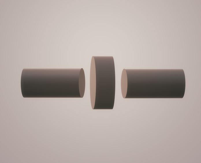 Regards, Marathonman |
|
|
|
Post by Marathonman on Feb 18, 2020 10:48:56 GMT -6
Faraday's Law;
Electric current is only induced in a coil of wire if the magnetic field is moving, increasing or decreasing in flux relative to the coil. Faraday's Law gives the electromotive force (emf) ε produced in a coil by a magnetic field:  In other words, the emf (electric potential) induced in the coil is proportional to the rate of change of flux linkage. In practice, this means that if the coil is stationary relative to the magnetic field, no emf is induced. In order to induce emf, either the coil or the magnetic field must move, increase or decrease. Alternatively, we may change the number of coil loops in the circuit as this will increase the flux associated with that circuit producing EMF. (Part G)
Lenz's Law;
Lenz's Law describes the direction of the current / emf induced by a change in magnetic flux. It states that current induced opposes the magnetic field. It does this by creating its own magnetic field (Flux linking). This explains the minus sign in Faraday's Law. this also means that the flux induced by a current (not a change in current) is proportional to the current, since the flux is produced in response to the current yet in the Figuera part G it is the adding of winding's which increases the flux which increases the opposition to the original current flow. So, a change in flux induces a current and a voltage which is proportional to the rate of change of flux. This fits with Ohm's Law (V = IR). A current and a voltage in a coil induce a flux which is proportional to the current and the voltage. These are the exact criteria Figuera used in his part G active inductor controller to control current flow of two feeds 180 degrees out from each other in complete unison. as the brush rotates each side of the brush is either adding or subtracting winding's that magnetically link to each side of the circuit increasing or decreasing the flux associated that half of the circuit. as we all know according to Faraday any change in flux produces an EMF and according to Lenz's Law being produced within the circuit itself will oppose the original current flow. what is changing as the winding's are added or subtracted is the associated flux with that half of the circuit which is the magnetic flux to current ratio which in turn reduces the original current flow. when you increase and decrease the current flow you give DC current frequency which then falls under the realm of inductive reactance. With the original current flow flowing through the wire and a continuous addition or subtraction of winding's that magnetically link to the circuit causes the flux to increase or decrease so according to Faraday's Law it will create an EMF and according to the Lenz's Law it will oppose the original current flow. More flux less current flow, less flux more current flow. For all you status quo and University classically trained people any time you change the magnetic flux to current ratio you have current reduction. What Figuera did was take a static inductor to an active position in a circuit which can and will control current flow in the most efficient manor on this planet storing and releasing it's magnetic flux into the system. Sorry for all you people that still think Figuera used a resistor network in his device as that would be wasteful and foolish as all potential converted to heat is non recoverable. Physics fact are just that, FACTS ! and can not be denied or refuted. Please do your proper homework, research and bench work to verify all that i have posted as you will be pleasantly surprised that part G is in fact an active Inductor Controller that controls current flow of two feeds in a linear fashion. Regards, Marathonman |
|
|
|
Post by Marathonman on Mar 11, 2020 8:02:25 GMT -6
Please keep in mind the starting supply and the secondary feed back is routed through part G to regulate the amount of current flow through the device otherwise the device would self destruct. Part G is the regulator as per the amount of saturation of the core. When the core approaches saturation the amount of output from the core will be attenuated thus being attached to the primaries will attenuate the potential through them reducing the output of the secondaries thus the secondary feed back into part G.
Obviously when testing this will not be the scenario but must be followed when the entire system is assembled. Without this key feature the device will run away and self destruct so please keep this in mind as the opposing fields and the saturation of part G keep things in check.
Part G simply directs current more to one side then the other continuously which in it's process stores and releases potential basically conserving the potential of the exciting side of the system which magnetically acts upon another magnetic secondary side of the system to produce an output. Neither of the parts of the device magnetically link to each other allowing the device to self sustain. Part G does not magnetically link as it's fields are opposing allowing both sides to control either set of electromagnets separately yet in complete unison.
The primaries and secondaries do not magnetically link either which will allow then to produce a substantial output without draining the inducing power supply like that of a standard transformer. If they link like that of a transformer the supplying power will be hit with a substantial drain as the secondary is added which will magnetically link to the system.
The Figuera device has NO SUCH LINKING allowing it to produce more then it takes to power it because the inducing side is never taxed since they (the primary and secondary) are opposing at all times and it stores and releases potential to off set any drop in potential from the rising side storing into the magnetic field like all coils do.
Regards,
Marathonman
|
|


