|
|
Post by Admin on Sept 11, 2019 11:38:03 GMT -6
This is for all members to discuss any and all things about the electronic switching of part G is conjunction with Creasysee's electronic build thread. MM  |
|
|
|
Post by Marathonman on Sept 11, 2019 11:58:59 GMT -6
I have found a circuit that is much more simple then Creasysee's circuit as it uses less chips to implement the same shift right/shift left sequence. it uses a 74HC595 and needs only 3 data lines plus power/ground to the Arduion using the shift out commands already within Arduino code. you can use the circuit below adding as much shift registers you need to achieve your output channel needs. i am a little confused as the use of the 10k resistor at the bottom of the circuit though, can anyone explain the use of this additional resistor.? below is the circuit. Regards, Marathonman  |
|
cheors
Junior Member

Posts: 33
|
Post by cheors on Sept 11, 2019 12:58:19 GMT -6
May be you don't need any shift register.
Arduino program can do that for you:
Example :
...................
PORTD =0b10011111; // Bits 5 6 = 0
delayMicroseconds(T2); // Overlap
PORTD =0b10111111; // Bit 6 = 0
delayMicroseconds(T1); // Step
PORTD =0b00111111; // Bits 6 7 =0
delayMicroseconds(T2);
PORTD =0b01111111; // Bit 7 = 0
delayMicroseconds(T1 );
PORTB =0b11111110; // Bits 7 8 = 0
delayMicroseconds(T2);
PORTD =0b11111111; // Bit 8 = 0
delayMicroseconds(T1);
|
|
|
|
Post by Marathonman on Sept 11, 2019 21:04:21 GMT -6
I am aware of this but look at the wire count to the Arduino. i have a Tensy 3.6 that has almost 60 pins but it is 3.3 volts. not only that the Sketch would be to complicated for me as i an a newbie when it comes to programming. with the shift registers i only need 6 shift registers, three plus wires plus power and ground with a small sketch.
i am not saying it can not be done it is just i don't want to get that deep into it right now. it quite possibly would be a good idea for you to head that avenue and post your work hear on this thread to support the electronic switching folks.
This guy in this video is a professor at some college that teaches an electronic class. the first chip in the video is pure junk but the second chip at 8 minutes in is an 74HC595 shift register which is a fantastic chip he demonstrates so well with the sketch to boot. at the end of the video he shows a 16 led circuit and adds maybe few extra lines and code change to switch it.
video below is fantastic i think.
Marathonman
|
|
|
|
Post by Marathonman on Sept 12, 2019 12:27:23 GMT -6
Here is the schematic for the circuit which is fairly simple. people say this shift register 74HC595B can not shift forward and backwards, well, all i can say you better tell the above professor that teaches electronics in Ireland he is wrong. the above video at 8 minutes in is the 74HC595B at work as you see it is much better then that of the junk before it. at the end of the video has does 16 LED's and adds a few line with the addition of one wire. below is the schematic for the 8 LED's and the code to run on Arduino. Marathonman  /* Test circuit of the 74HC595B shift register Serial to Parallel Converter. the 8 LED's light for one second exactly on each pass. by Derek Mallow. lower the time increase the speed ie... Frequency. change to microseconds if needed. */ const int clockPin = 9; // Clock sequence to "Arduino" pins can be changed to what ever you have on your board. const int dataPin = 8; // Serial data line const int latchPin = 10; // Latch Pin void setup() { // happens once on startup pinMode(clockPin, OUTPUT); pinMode(dataPin, OUTPUT); pinMode(latchPin, OUTPUT); } void loop() { for (int i=0; i<8; i++) { shiftOut(dataPin,clockPin, MSBFIRST,B00000001 << i); digitalWrite(latchPin, HIGH); delay(125); // 125*8 is one second digitalWrite(latchPin, LOW); } for (int i=0; i<8; i++) { shiftOut(dataPin, clockPin, MSBFIRST, B10000000 >> i); digitalWrite(latchPin, HIGH); delay(125); // 125*8 is one second digitalWrite(latchPin, LOW); } } i will copy the added lines needed for the 16 LED sketch that need to be added the more the 74HC595B's you add to the system. this set up saves all kinds of time and money as the circuit only uses 1 arduino and 1 chip per 8 channels of switching. each additional chip adds 1 line extra to the Arduino. Marathonman |
|
|
|
Post by Marathonman on Sept 12, 2019 14:25:03 GMT -6
here is the 16 LED code for the Arduino sketch. study the video presentation as he explains the changes and highlights them as he goes. with that knowledge in hand people should be able to have many chips daisy chained to an Arduino to switch the electronics on top of part G.
with the code below the wiring is the same except for the added data line from the second shift register to the Arduino which is pin 11 on the Arduino.
insert code here[code]

/* Test circuit of the 74HC595B shift register serial to parallel Converter

   16 Leds in sequence up then back by Derek Mallow.

*/


const int clockPin = 9;  // Clock Sequence

const int hdataPin = 8;  // MS byte Serial data line

const int ldataPin = 11; // LS byte Serial data line

const int latchPin = 10; // Latch Pin


void setup() { // happens once on startup

  pinMode(clockPin, OUTPUT);

  pinMode(hdataPin, OUTPUT);

  pinMode(ldataPin, OUTPUT);

  pinMode(latchPin, OUTPUT);

}


  void loop() {

    for (int i=0; i<16; i++)

    {

      if(i<8)shiftOut(ldataPin, clockPin, MSBFIRST, B00000001 << i);

      else shiftOut(hdataPin, clockPin, MSBFIRST, B00000001 << i-8);

      digitalWrite(latchPin, HIGH);

      delay(62);

      digitalWrite(latchPin, LOW);

    }

      for (int i=0; i<16; i++)

  {

      if(i<8)shiftOut(hdataPin, clockPin, MSBFIRST, B10000000 >> i);

      else {

      shiftOut(hdataPin, clockPin, MSBFIRST, B00000000);

      shiftOut(ldataPin, clockPin, MSBFIRST, B10000000 >>i-8);

      }

      digitalWrite(latchPin, HIGH);

      delay(62);

      digitalWrite(latchPin, LOW);

      }

  }
[/code]
Marathonman
|
|
|
|
Post by Marathonman on Sept 12, 2019 14:28:56 GMT -6
cheors;
can you do a few posts on the Arduino shift registers and what it takes to do so if you can. i would love to learn more about them.
Thanks,
ALL;
what i found last night with the coding from Dereck Mallow was with the above electronic switching, one line needs to be added to the Arduino each time an 8 channel chip is added to the circuit and that would be the ldataPin through out the code. to keep things from getting mixed up i labeled the ldataPins, ldata1Pin, ldata2Pin, ldata3Pin, ldata4Pin ect... which identifies each added chip serial data line that corresponds to the Arduino pin assigned to it. that way it might be easier to identify the added chips.
to test this i changed ldataPin, to ldata1Pin throughout the 16 channel code and it compiled just fine so i know this pin numbering in code will work. mater of fact you do not even have to put hdata or ldata all you need to put is dataPin1 for the first chip, dataPin2 for the second, dataPin3 for the third ect, ect.. so with that being said i will need 46 to 48 channels on an my electronic part G when i can afford a new core. then when i add the secondary feed back the shift left shift right will be opposite of the shift of the positive brush to mimic the brush rotation just perfect which corresponds to the reducing side releasing potential into the system through the secondary feed back.
this program was heaven sent.
Regards,
Marathonman
|
|
cheors
Junior Member
Posts: 33
|
Post by cheors on Sept 13, 2019 1:19:33 GMT -6
Ok. My first attempt
Arduino Mega 54 bits check program :
/*
* Created: Cheors mar. avr. 17 2018
* Processor: ATmega2560
* Compiler: Arduino AVR
* Turn 54 bits on and off
*/
int X = 300;
void setup()
{
DDRA =255; // A...L direction registers as output
DDRB =255;
DDRC =255;
DDRD =255;
DDRE =255;
DDRF =255;
DDRG =255;
DDRH =255;
DDRJ =255;
DDRK =255;
DDRL =255;
}
void loop()
{
digitalWrite(0,HIGH); // Turn on one bit
delay(X);
digitalWrite(0,LOW); // Turn off
delay(X);
digitalWrite(1,HIGH); // Turn on next bit
delay(X);
digitalWrite(1,LOW);
delay(X);
digitalWrite(2,HIGH);
delay(X);
digitalWrite(2,LOW);
delay(X);
digitalWrite(3,HIGH);
delay(X);
digitalWrite(3,LOW);
delay(X);
digitalWrite(4,HIGH);
delay(X);
digitalWrite(4,LOW);
delay(X);
// // and so on......... // digitalWrite(52,HIGH);
delay(X);
digitalWrite(52,LOW);
delay(X);
digitalWrite(53,HIGH);
delay(X);
digitalWrite(53,LOW);
delay(X);
}
|
|
cheors
Junior Member
Posts: 33
|
Post by cheors on Sept 13, 2019 1:40:10 GMT -6
But you could also write :
void loop()
{
PORTA = 0b00000001;
delay(X);
PORTA = 0b00000000;
delay(X);
PORTA = 0b00000010;
delay(X);
PORTA = 0b00000000;
delay(X);
PORTA = 0b00000100;
delay(X);
PORTA = 0b00000000;
delay(X);
//......
// Then next register
//
PORTB = 0b00000001;
delay(X);
PORTB = 0b00000000;
delay(X);
PORTB = 0b00000010;
delay(X);
PORTB = 0b00000000;
delay(X);
PORTB = 0b00000100;
delay(X);
PORTB = 0b00000000;
...................................
|
|
cheors
Junior Member
Posts: 33
|
Post by cheors on Sept 13, 2019 1:42:17 GMT -6
Or : PORTA = 1; PORTA = 2; PORTA = 4; ......
|
|
cheors
Junior Member
Posts: 33
|
Post by cheors on Sept 13, 2019 1:50:03 GMT -6
THE BIG DIFFERENCE :
PORTX command takes less than 400nS
digitalWrite command takes 5 to 6 uS
PORTX is about 10 times faster
(I didn't experiment. Only simulation program timing results)
|
|
|
|
Post by Marathonman on Sept 13, 2019 11:49:59 GMT -6
I to have learned last night the digitalWrite and shiftOUT commands are slow. the direct port command are much, much faster and would essentially be better but then again i have 46 channels that could quite possibly run on the shiftOut and digitalWrite commands. one revolution of the brush will be at 16.66 ms which will then be divided between the contacts. so if i have electronic switching it must be shifted left starting at pin one of the first shift register going to the last shift register's last pin then shift right back to the first pin of the first shift register in 16.66 ms.
another thing i realized is the 74HC595B form Nexperia which can hit 100 Mhz has the ability to connect the stcp store register (Latch) input to the shcp shift register input. by tying them together with the same clock the store register (Latch) is delayed 1 clock cycle which can increase the speed of shift,store function using only one input clock signal. this is something VERY overlooked by everyone but i need to test this out first. the shiftOut and digitalWrite commands are wholly dependent on the frequency of the Arduino clock in the first place so a faster clock the faster the Write shift commands are executed.
Marathonman
|
|
cheors
Junior Member
Posts: 33
|
Post by cheors on Sept 13, 2019 15:05:16 GMT -6
Use delayMicroseconds statement instead of delay.
This 46 bits shift routine loops within 16.68 mS Loop16mS.txt (6.61 KB) |
|
|
|
Post by Marathonman on Sept 13, 2019 15:46:17 GMT -6
EDIT; i deleted the calculation as i was forgetting the full loop not just half of a rotation. see below post.
i think there is a better shorter way to code using the same ports as you did and micro delay which will cut the coding by a third. i will discuss on the Arduino forum.
what i need to know is what is the delay of the direct port manipulation turning on then turning off is of a regular 16mhz 5 volt Arduino as this would help dial in the delay.
Cheros; that give a total of 60.048 Hz which is very good indeed.
thanks again,
Marathonman
|
|
|
|
Post by Marathonman on Sept 13, 2019 20:03:26 GMT -6
The channels are 46 in total total so up and back will be 92 plus two added for the ends on longer so i have to divide 16.666 ms per revolution by 94 up and back total. so i have 16.666 ms per rotation of the channels up and back to mimic a rotating brush at 3600 rpm. so that leaves me with each channel on for .177 ms each. each end together accounts for .177 uS x 6 = 1.062 mS, 88 channels x .177 mS = 15.576 mS + 1.062 Ms = 16.638 mS x 60 rps = 998.28 mS x 60 rpm = 59896.8 mS divided by 1000 = 59.896 Hz. i think i can live with 59.896 Hz. Below is a graph i made of the signal overlap that the electronic needs to incorporate for the Make Before Break for uninterrupted current flow through part G otherwise BEMF will form and your device will not work. Marathonman 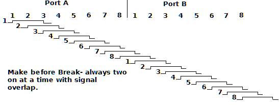 |
|


