|
|
Post by Marathonman on Oct 29, 2020 11:53:03 GMT -6
Electromagnets Wired specifically as Electromagnets
Ways to increase the speed of magnetic field build up of your primary sets of electromagnets. Since the whole point is to build electromagnets that are specifically electromagnets and not controlled by resistance. Why? because part G controls the current flow NOT the primaries so wind them specifically as electromagnets with as little resistance as possible. do not add more complexity then is needed as part G is the controller of current for the whole system. More resistance results in more wasted potential in the form of heat which is non recoverable. The whole Figuera system is very, very low resistance and the only part that is wound according to present day teachings is the secondary. Below pic is "One way" to reduce the overall resistance and increase the speed of the electromagnets which then will react to any such changes in current flow from part G in a very timely manor. This technique will allow the magnetic field line pressures to be maintained at all times. This does add a little more complexity to the winding of your primaries but the end results are what counts reducing resistance and self inductance. If you wind your primaries with one long wire you will be slammed into the resistance, self inductance wall and end up with very slow acting primaries that are unable to respond to part G's current fluctuations in a timely manor thus loosing field line pressures between the primaries with an output that will plummet to almost zero. Our goal here is to maintain field line pressure through out the entire sweep of the secondary from side to side or rather the primaries from high to low. Please remember that all primaries "MUST BE EXACT COPIES" of each other which will aide in the final balancing of the device.  Regards, Marathonman |
|
|
|
Post by Marathonman on Nov 30, 2020 21:40:48 GMT -6
For those who are really serious about building the Figuera device and trying to figure out how part G works then please research the technology behind Magamps, core saturation, self inductance, inductive reactance, magnetic linking, Faraday's inductive Law, and lastly the Lenz Law. What you will find is all of these are related through flux and the proper manipulation of it. The Figuera part G is no different and as such is so exactly like a variac you have no clue with one exception.
One device uses AC and the other uses DC and i will leave it to you to decide which is which. I will tell you this, both rely on some kind of movement according to Faraday's induction law so it is up to you to figure out what definition of movement was Faraday referring to in order to attain an EMF. Thus how to use that flux to oppose the current that created it in the first place ie... vary the opposing flux to control the actual current flow that created it in a non destructive non heat death fashion opposite of what resistors do. Remember AC reversal has absolutely nothing to do with this correlation what so ever, it is the continuous rise and fall of current "ONLY". Regards, Marathonman |
|
|
|
Post by Marathonman on Dec 8, 2020 18:32:21 GMT -6
An inductor coil has a central core area, ( A ) with a constant or changing number of turns of wire per unit length, ( l ). So if a coil of N turns is linked by an amount of magnetic flux, Φ then the coil has a flux linkage of NΦ and any current, ( i ) that flows through the coil will produce an induced magnetic flux in the opposite direction to the flow of current. Then according to Faraday’s Law, any change in this magnetic flux linkage produces a self-induced voltage in the single coil which is in the opposite direction opposing the original flow.
Just as it says, "ANY" change in magnetic flux linkage be it increasing or decreasing will create a self induced voltage. So then we have the Figuera device specifically part G active inductor controller that does just that. It changes the flux linkage per each side of the brush either increasing it's winding count or decreasing it's winding count to set N and S which has just fulfilled the exact requirements to produce EMF according to Faraday in 1831.
If you increase the winding's within the time constant of the circuit as per the same amount of current flow you will have increased the magnetic flux associated with that circuit and since it was created within the circuit it self according to Lenz's Law, it will oppose the original flow that created it in the first place.
Of course you have to have the proper amount of winding's to do this. Doh !
Regards,
Marathonman
|
|
|
|
Post by Marathonman on Jan 18, 2021 9:33:45 GMT -6
Four Pole vs Two Pole
When you have a standard generator you have four poles, a north/south and a south/north to get the reversal of the current as the fields travel is in the opposite direction with AC output as the consequence. In order to get the same scenario in the Figuera device he used two opposing poles that are the same direction when looking at the pole faces side by side yet when put end to end facing each other with the secondary between them they are in the OPPOSITE DIRECTION. Being opposite spin direction the Figuera device fulfill the same AC requirement as a standard generator yet only using TWO POLES. Yes!, the Figuera device fulfills the AC requirement generation because each electromagnet occupies the secondary one at a time when switching from high to low, low to high and being opposing there will not be any direct linking like that of a transformer that causes an extra load on the source. Also being opposing, the two primary electromagnets compress the field lines to match the high intensity field of a standard generator which also causes the bulging of the magnetic and electric fields. These bulging fields can be harvested by placing a larger diameter secondary between them to increase the secondary output even farther. This action can NOT be done with a standard generator as the high intensity fields remain compressed as they flow from north to south. Please!, study the graph below and you will realize that the Figuera device fulfills the same reversal of field lines as a standard generator does yet using only TWO POLES. 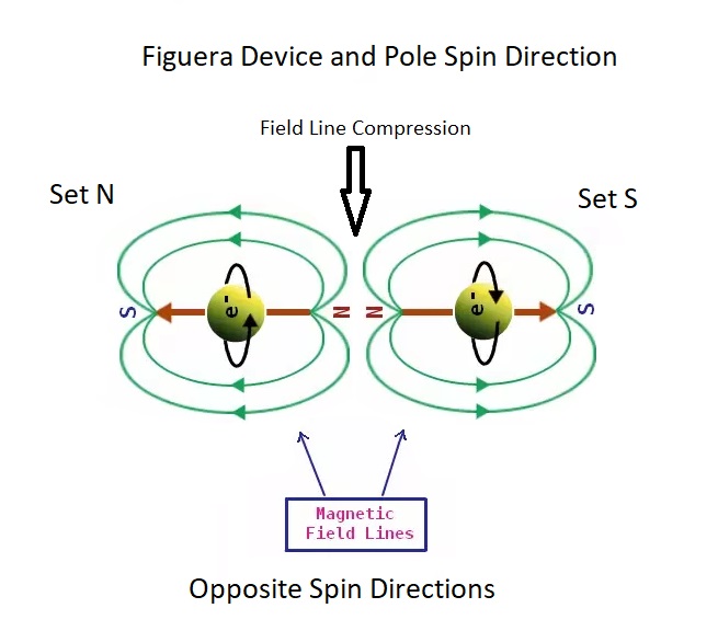 Just because the researcher/replicator is getting nothing out of their device doesn't mean it doesn't work. All this means is YOU have something wrong in your device like not enough compression or lack of proper sweeping. Getting it right in the sweet spot you will know as you output will rise considerably. Remember Figuera had a working device when he went to the patent office all FIVE TIMES ! Regards, Marathonman |
|
|
|
Post by Marathonman on Feb 19, 2021 11:06:19 GMT -6
Resistors vs. Inductors
Inductors do not behave the same way as resistors do. Whereas resistors simply oppose the flow of current through them (by dropping a voltage directly proportional to the current) and as such power is wasted in the form of heat which is NON recoverable. Inductors oppose changes in current through them by dropping a voltage directly proportional to the rate of change of current which is induced in the reverse direction. Remember increasing current increases stored potential decreasing voltage and decreasing current releases stored potential into the system increasing voltage.
In accordance with Lenz’s Law, this induced voltage is always of such a polarity as to try to maintain current at its present value. That is, if the current is increasing in magnitude, the induced voltage will “push against” the current flow; if the current is decreasing, the polarity will reverse and “push with” the current to oppose the decrease.
So as one would conclude from this statement that the more winding's you have per the given current the more inductance you will have. Increasing the size of the circuit will in fact according to Faraday's induction law increase the opposition to the original current flow. This is accomplished by magnetically linking each additional winding to the circuit increasing the overall inductance of the circuit thus decreasing current flow.
Negative Power?
But what does negative power mean? It means that the inductor is releasing power back to the circuit, while a positive power means that it is absorbing power from the circuit. Since the positive and negative power cycles are equal in magnitude and duration over time, the inductor releases just as much power back to the circuit as it absorbs over the span of a complete cycle.
What this means in a practical sense is that the reactance of an inductor dissipates net energy of zero, quite unlike the resistance of a resistor, which dissipates energy in the form of heat, (non recoverable). Mind you, this is for perfect inductors only, which have no wire resistance. all the energy feed into the inductor is not wasted like that of a resistor as it is stored into the magnetic field. Inductors store a magnetic field and capacitors store an electric field which both are considered kinetic energy.
Given any such current supply fed into an inductor it will oppose the change for only the time constant of the circuit then return to a steady state. but wait one moment, we do NOT have a static inductor in the Figuera device, what we have is an active inductor that has a moving positive brush that changes the size of the circuit of two feeds on a continuous basis and as such have ongoing induction change on both feeds or legs coming into part G from set N and set S.
Going back to the fact that all inductors store into the magnetic field and resistors waste potential in the form of heat non recoverable. Thus in the Figuera device we have an active inductor controller that is split into two halves and as such will control two feeds separately yet in complete unison all while storing and releasing potential at the same time from both halves. One is storing the other is releasing at the same time then vise verse continuously.
Since these actions are within the time constant of the circuit you end up having an orderly rise and fall of induction of both feeds which is the rise and fall of the opposition to the original current flow.
The end result is the most efficient way to control current flow on this planet and with two inductors in one, you have one feeding the other which offset the drop in voltage as it is storing into the field. Adding the secondary feedback into the system not only replaces losses occurred but give rise to amplification to the rising primaries to replace the loss of pressure from reducing one set of primaries to get the sweeping action across the secondary while the other is increased. This will maintain the compression of both fields as per your required output needs.
In this action of one primary rising and the other falling, both electric fields are in complete coherency..ie.. the same direction which support each other. Yet the same instances the magnetic fields are always opposing and in different direction. (spin) every half cycle there will be a polarity change as the direction of the induced is changed as in the direction of the electric field. Each primary occupy the secondary one at a time as the other field is pushed out of the secondary as the other is filling up the secondary then reducing creating the induction of the secondary.
There is no direct linking to the primaries like that of a transformer. It is a soft coupling on the reduction phase of the reducing primaries which induce the secondary therefore the lenz law is NOT applicable in this situation as there is no huge hunk of spinning iron. As the increasing primaries are filling up the secondaries the reducing primaries do not see this because they are OPPOSING in nature yet BOTH are accountable for the required pressure of induction of the secondaries.
Regards,
Marathonman
|
|
|
|
Post by Marathonman on Mar 1, 2021 9:38:47 GMT -6
Please keep in mind that the above previous post, both cycles are happening at the same time. one is rising, storing into the magnetic field while the other is releasing it's store magnetic field into the system to off set the rising side. Together with the secondary feed back they forward bias the rising side which replaces the reduction of pressure of the reducing side in order to get the sweeping action across the secondary. The addition of the secondary with the reducing side forward biases the rising primaries which allow it additional magnetic field thus maintaining the pressure between both primaries. This mix of potential happens in part G so part G can be considered an amplifier of the original signal as the voltage potential rises above the starting potential thus forward biasing the rising primaries allowing more current to flow through them.
The whole point of this is to compress the field lines to match the intensity of a standard N/S generator the shift the fields back and forth letting each electromagnet with different spin directions occupy the secondary then induce while reducing.
All this while maintaining the pressure between them and avoiding the pitfalls of direct coupling of a standard generator. (Lenz Law Dilemma)
Regards, Marathonman |
|
|
|
Post by Marathonman on Mar 2, 2021 21:49:44 GMT -6
Inductive reactance controlling current flow
That is, as the impedance increases, the current decreases. If you expand the circuit within the time constant of said circuit with any such given static current, you will according to Faraday have created an EMF in said circuit. Since the EMF was created within the circuit it self, it will according to the Lenz law oppose the original current that created it in the first place. If you expand the circuit you increase the inductance which increases the inductive reactance which will oppose the original current flow even with a static current. Thus in the Figuera device controller you are using inductive reactance to control current flow of two feeds in complete unison all while storing and releasing said energies to aide the system not oppose it. Resistor are a washout because they are completely wasteful as all heat generated is lost and NON RECOVERABLE. So all you ney sayers have to ask your selves which would be more efficient in a system that needs to be a self runner. choose the heat death resistor or use an inductor that allows you to reuse the stored energy that was once used to control current flow. I have to admit for me it was not a very hard choice to come to with such a logical conclusion. Expand the circuit, increase inductance, increase the opposition to the original current flow decreasing current flow, giving frequency to DC thus falls under inductive reactance. FYI; " ANY" change in current flow how ever produced, falls under Inductive Reactance even if it was created by an increase in inductance or whether it was DC given frequency it is still Inductive Reactance. EDIT; The positive rotating brush on the inductive controller is causing a time varying magnetic field through flux linking with the addition or subtraction of winding's. This in turn changes the inductance values which according to Faraday in 1831 " Any change in flux creates an EMF" and according to the Lenz law it will oppose the original as the voltage created is in the opposite direction. this is physics facts and as such can not be denied by anyone.
Irregardless of your opinion that DC can not be given frequency or that an inductor can not control current flow is completely irrelevant uneducated opinion in this situation that is completely backed by PHYSICS and FARADAY.Regards, Marathonman |
|
|
|
Post by Marathonman on Mar 3, 2021 4:42:37 GMT -6
Series VS Parallel The graph below was taken from an early 1900 book on magnetism and electromagnets. Basically what it stated and back up with the graph below was that with a steady state current flow a series winding setup was better choice, B being series and C being parallel. With a rising and falling current flow the the ability of the parallel coils were far superior to the series winding as the current rose much, much faster and thus producing a magnetic field in turn with the changing current, line A.
One large winding or series of winding's is "NOT" the way to go. you must use parallel winding's on your primaries to react as quick as possible to part G's current changes giving it the ability to maintain the required compression of field lines between primaries. Series winding's are just to slow to keep up with the current changes of part G because from self inductances and resistance slowing it down,
The proof is in the pudding below line A parallel rate of current increase is far, far superior then that of line B series which is just to slow to keep up with the current changes of part G.
Granted the series ampere turn is better in series winding yet at an expensive cost being to slow. Additional winding's on parallel to compensate the reduced ampere turn is a must and easily applied all attaining the perfect fast responding electromagnet you can get.
Parallel aeries winding primaries is a key element in this device as according to the graph below the the parallel windings are twice as fast as the regular winding.
.

Regards,
Marathonman
|
|
|
|
Post by Marathonman on Mar 7, 2021 17:13:13 GMT -6
The average power consumed by the Figuera active inductor controller is ZERO! WHY ?
Having the inductor split into two halves gives the inductor the ability to control two feeds at the same time independently yet in complete unison. While one side is on the rise which is storing into the magnetic field thus a voltage drop will occur. The other side is falling thus is releasing potential back into the circuit increasing the voltage which off set each other thus zero consumed.
Since all of man's devices have losses in it's electrical operation, this device is no different and as such must be compensated to replace losses. Also in the process of reducing one set of electromagnets to get the sweeping action across the secondary, a loss of field line compression will occur between the electromagnets. The reduction of one third of one electromagnet (according to build parameters) in this sweeping action which is one sixth between both magnets. This reduction of pressure MUST be replaced or on going induction will be reduced.
This is where the secondary feed back comes into play replacing the losses occurred and replacing the reducing pressure. In other words the secondary feed back will add to the reducing side of the system giving rise to amplification of the original potential to the rising primaries. This forward biasing action allows the Figuera device to maintain the needed field line pressure to maintain your required output indefinitely.
Remember we are using DC which is given frequency which is entirely dependent on the brush rotation which expands and contracts both circuits at the same time opposite of each other. This allows a continuous magnetic flux linking induction to take place ie.. a time-varying magnetic field inducing electromotive force in the inductive controller, described by Faraday's law of induction in 1831 which reduces and increases current flow of both feeds thus falls under inductive reactance.
Regards,
Marathonman
|
|
|
|
Post by Marathonman on Mar 18, 2021 12:57:14 GMT -6
Self Inductance/Inductive Reactance
To all those people from other sites that opposed for years the thought that an inductor can't control current flow i remove my hat, fall on the floor and bust up laughing hysterically until my gut hurts. According to Faraday in 1831 "ANY, change in flux will create EMF" notice he never said a change in current flow just a change in flux associated with the circuit. Does not an increase in the size of the circuit constitute an increase in associated flux?  you darn right it does. ANY time you add a loop to a circuit you are increasing the associated flux of that circuit as per ANY given current EVEN IF THAT CURRENT IS STEADY DC. As long as you continuously add or subtract winding's from said circuit within the time constant of said circuit you will attain a steady increase or decrease of said flux. Since it was created within the circuit it self, according to the Lenz Law it WILL OPPOSE the original current that created it in the first place. Thus ANY change in an Inductor circuit as in the Figuera active Inductor controller will in fact according to " REAL PHYSICS", will create EMF in the opposite direction giving you the ability to control DC current flow of two separate feeds in complete unison.
ANY INCREASE IN LOOP COUNT INCREASES FLUX AND AN INCREASE IN FLUX CREATES EMF, unless you think FARADAY IS WRONG ! and YOU KNOW BETTER EF and OU..... (Laughing hysterically) 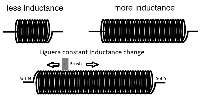 Case was proved a long time ago and verified by multiple researchers and by Physics majors yet i do like rubbing it in your face once and a while. Regards and still right, Marathonman |
|
|
|
Post by Marathonman on Apr 4, 2021 8:38:06 GMT -6
Two for the Price of One!
The properties of the Figuera active inductor controller is exactly the same properties as an Magamp with one exception, having two current controlling lines instead of one. They both are using inductive reactance to control current which opposes the original current flow. Since the Magamp has a lot of inductive reactance on the AC winding without the control winding almost no current will flow. With the Figuera active inductor controller being DC operated the circuit has to be continuously increased and decreased to attain continuous ongoing induction thus the reason for the rotating positive brush. This rotating positive brush expands and contracts both circuits in complete unison yet completely opposite from each other. This action allows one feed to increase in current flow while the other is decreasing in current flow. These action allow the Figuera active inductor controller to control two feeds coming from the two sets of electromagnets, which are wound specifically as electromagnets to attain the most intense magnetic field and speed of increase as possible allowing them to stay in unison with the constant current change from the controller. Please remember the controller controls the current flow NOT the primaries so please wind them specifically as electromagnets. Bottom line is the Figuera active inductor controller is in a constant state of flux change from the increase and decrease of both circuits which according to Faraday in 1831 "ANY change in flux creates EMF" and according to the Lenz Law it will oppose the original current flow that created it in the first place. Word of advice, when winding your active inductor controller the winding's need to be right next to each other to attain the highest proper inductance to control current flow which is exactly like a magamp and the inductive reactance properties within. Regards, Marathonman |
|
|
|
Post by Marathonman on Apr 18, 2021 21:26:59 GMT -6
Here is the video i have been promising for a while. this video will explain a few technical details surrounding the Figuera part G active inductor controller. i surely hope you enjoy this video and please if you have any questions please feel free to ask away. i am here for humanity not my own personal gain so i hope you realize this through my dedication to this device and years of constant pursuit.
EDIT: I made a serious mistake in this video that I need to correct. I realized I was referring to an AC varic instead of a MAGAMP. Some how I had gotten the two mixed up in my head. What I should of done was write it down on paper first then reviewed it as I then would of caught it. Instead I did this video with NO rehearsal what so ever. I apologize for my insane mistake. MAGAMPS have inductive reactance not variac's as variac's use transformer action.
Regards, Your friendly humanitarian and real human being, Marathonman |
|
|
|
Post by Marathonman on May 2, 2021 16:58:55 GMT -6
"The Electromagnet,and Electromagnetic Mechanism" S.P.Thompson 1891.To project or drive the magnetic lines across a wide intervening air-gap requires a large magnetizing force, on account of the great reluctance and the great leakage in such cases; and the great magnetizing force cannot be achieved with short cores, because there is not, with short cores, a sufficient length of iron to receive all the turns of wire that are in such a case essential. The long leg is wanted simply to carry the wire necessary to provide the requisite circulation of current. We now see how, in designing electromagnets, the length of the iron core is really determined; it must be long enough for to allow of the winding upon it of the wire which, without overheating, will carry the ampere-turns of exciting current which will suffice to force the requisite number of magnetic lines (allowing for leakage) across the reluctances in the useful path. This is the reason for the 2:1 (or higher) ratio of primaries to secondaries to account for this added reluctances of not only the gap between them but the included air return path. Also the resemblance of stacking magnets to achieve a higher magnetizing force, the sectioning of winding's in parallel will not only achieve this and yet at the same time increase the speed of the electromagnets to coincide with the fluctuating current. assembling the primary electromagnets specifically as electromagnets and the parallel winding technique will achieve this requirement yet you must account for the added reluctances of the air paths in your calculations and pressures needed between them to achieve your desired secondary output. A rough and ready rule sometimes given for the size of wire is to allow of a 1/1000 th square inch per ampere. This is an absurd rule, however, as the figures in the table show. Under the heading 1000 amperes to square inch, it appears that if a No. 18 S.W.G. wire is used, it will at that rate carry 1.81 amperes ; that if there is only one layer of wire, it will only warm up 4.64 degrees Fahr., consequently one might wind layer after layer to a depth of 3.3 inches, without getting up to the limit of allowing one square inch per watt for the emission of heat In very few cases does one want to wind a coil so thick as 3.3 inches. For very few electromagnets is it needful that the layer of coil should exceed 1/2 an inch in thickness; and if the layer is going to be only 1/2 an inch thick, or about one-seventh of the 3.3, one may use a current density *V /7 times as great as 1000 amperes per square inch, without exceeding the limit of safe working. Indeed, with coils only 1/2 inch thick, one may safely employ a current density of 3000 amperes per square inch, owing to the assistance which the core gives for the dissipation and emission of heat. Suppose, then, we have designed a horse-shoe magnet with a core 1 inch in diameter, and that after considering the work it has to do, it is found that a magnetizing power of 2400 ampere-turns is required ; suppose also that it is laid down that the coil must not warm up more than 50 degrees Fahr. above the surrounding air temp. what volume of coil will be required ? Assume first that the current will be I ampere ; then there will have to be 2400 turns of a wire which will carry 1 ampere. If we took a No. 20 S.W.G. wire, and wound it to a depth of 1\2 an inch, that would give 220 turns per inch length of coil ; so that a coil 11 inches long, and a little over 1/2 inch deep (or 10 layers deep) would give 2400 turns. Now Table XV. shows that if this wire were to carry 1.018 ampere, it would heat up 225 degrees Fahr., if wound to a depth of 3.9 inches. If wound to 1\2 inch, it would therefore heat up about 30 degrees Fahr. ; and with only 1 ampere would of course heat less. This is too good ; try the next thinner wire. No. 22, S.W.G. wire, at 2000 amperes to square inch, will carry 1.23 ampere; and heats 225 degrees fahr if wound up 1.13 inch. If it is only to heat 50 degrees fahr it must not be wound more than 1\4 inch deep ; but if it only carries current of 1 ampere it may be wound a little deeper say to 14 layers. There will then be wanted a coil about 7 inches long to hold the 2400 turns. The wire will occupy about 3.85 square inches of total cross section ; and the volume of the space occupied by the winding will be 26.95 cubic inches. Two bobbins, each 3-1\2 inches long and 0.65 deep, to allow for 14 layers, will be suitable to receive the coils. By the light of the knowledge one possesses as to the relation between emissivity of surface, rate of heating by current, and limiting temperatures, it is seen how little justification there is for such empirical rules as that which is often given, namely, to make the depth of coil equal to the diameter of the iron core. Consider this in relation to the following fact ; that in all those cases where leakage is negligible, the number of ampere-turns that will magnetize up a thin core to any prescribed degree of magnetization will magnetize up a core of any section whatever, and of the same length, to the same degree of magnetization. A rule that would increase the depth of copper proportionately to the diameter of the iron core is absurd. Where less accurate approximations are all that is needed,more simple rules can be given. Here are two cases; Case I. Leakage assumed to be negligible. Assume B = 16.000, then H = 50 (see Table IV). Hence the ampere turns per centimetre of iron will have to be 40, or per inch of iron, 102; for H is equal to I.2566 times the ampere-turns per centimetre. Now if the winding is not going to exceed 1\2 inch in depth, we may allow 4000 amperes per square inch without serious over-heating. And the 4000 ampere-turns will require a 2-inch length of coil, or each inch of coil carries 2000 ampere-turns without over-heating. Hence each inch of coil 1\2 inch deep will suffice to magnetize up 20 inches length of iron to the prescribed degree. Case 2. Leakage assumed to be 50 per cent. Assume B in air gap = H = 8000, then to force this across requires ampere turns 6400 per centimetre of air, or 16,250 per inch of air. Now if winding is not going to exceed 1\2 inch depth, each inch length of coil will carry 2000 ampere-turns. Hence, 8 inches length of coil 1\2 inch deep will be required for 1 inch length of air, magnetized up to the prescribed degree. the later case #2 being more applicable to the Figuera device owing to the small core gap and the large return air path. as one can gather i myself, as well as many other researchers/replicators had miss interpreted or rather underestimated the reluctances of the reluctant air paths and as such my electromagnet, in a larger form, had not enough force to project it's proper path of operation. i am recalculating the primaries for such a higher force of projection. i will be also incorporating sectional winding techniques with a larger amount of winding's, then paralleled. I also ground the corners of the primary cores to alleviate the problem of winding a square corner, which by the way causes bulging of the winding at those points. this reduces the inductance and adds to the cost of more wire used. these reasons above are the sole contributor to replicators attaining such low inductances. Regards, Marathonman Attachments:
|
|
|
|
Post by Marathonman on May 28, 2021 10:37:11 GMT -6
Inductance controlled impedance changer, Figuera's Active Inductor Controller
Magnetic flux controls current.
The active inductor contoller uses one large inductor then splits that inductor in two with the use of two opposing magnetic fields at the positive brush then uses a variation of magnetic flux to control the two feeds in complete unison 180 degrees from each other. With the use of a constant rotating positive brush Figuera was able to alter the size of the circuit of both feeds on a continuous basic which is needed as the power source is DC thus the reason for the constant rotation. The rotation speed can then be set to achieve the desired output hertz required in the country you reside in. Figuera utilized the Lenz Law to his advantage in his controller knowing any addition of winding's to the circuit will in fact increase the flux for that half of the circuit. Being in such close proximity to the other winding's the magnetic field interacts with the winding next to it thus producing an EMF in the opposite direction to the original current flow. Since the device is DC operated the constant increase and decrease of both circuits is needed in order to give DC, AC like quality of frequency, which then falls under inductive reactance, which can then be utilized to control current flow of both feeds. The patent states the use of a twenty horsepower AC motor in addition to the house lights and the outer street lights in front of his house being powered by his device. there is no mention of the actual use of the motor which is inconsequential of the real purpose of the motor. The active inductor controller will have current lag voltage by 90 degrees which will in essence throw the timing of the device off, which will then produce substantially less output. In the AC motor the current will lead voltage by 90 degrees thus will cancel out the inductor's lag of current and in turn keeping the timing of current and voltage in proper phase alignment. This and the fact that the device will always require a load to be present when in operation is the real reason for the twenty horse power motor irregardless of whether it is being utilized or not. With the motor preset the secondary output creates a secondary field along side the original field around the secondary. This secondary Lenz Law field is what is shoved back and forth across the electric field produced from the reducing primaries thus giving the illusion of motion to the electric field, in turn producing an EMF in the secondary. Without a load presented to the secondary the lenz law field will not form and thus the device will not produce an EMF in the secondary nor any feed back to the device.
When the are being swept from side to side the reducing primaries are creating the electric field while the rising primaries are not only shoving the lenz law field to the opposite side, it is also filling the secondary up with opposite flux at the same time. This flux can not be seen by the opposing primaries being reduced nor can the secondary as it's secondary field is opposing also. Remember the device is generating when one primary is being reduced and with opposing fields so the direct coupling of the primary does not take place like that of a transformer. These scenarios are two completely different operations and should not get confused with each other. Regards, Marathonman
|
|
|
|
Post by Marathonman on Nov 8, 2021 8:28:09 GMT -6
As everyone should know by now that reactive components dissipate zero power, as they equally absorb power from, and return power to, the rest of the circuit. Therefore, any inductive reactance in this load will likewise dissipate zero power. this i am referring to is part G as well as each set of electromagnets. The only thing left to dissipate power here is the resistive portion. This is where the secondary feed back comes into play to replace the ohmic losses inherent in mans systems of power generation. granted they are small yet still losses just the same. Also the reason this device can resist the starting power is the over all system voltage is much higher then the original starting power. When all three sources are present in the system, ie. part G, electromagnets and the secondary feed back, there will be an amplification of the original signal within part G as each one releasing it's potential will act as a series of batteries increasing it's voltage above the original starting potential. For this reason being so highly overlooked is the reason for many to believe that no device can be over unity. If one was to minimize the losses and return the potential back into the system when reduced is the key component to this device being able to self sustain. That and the fact that we are not rotating a huge hunk of iron yet instead moving the massless, weightless field back and forth over the secondary through the control of current flow.
So let me ask you this readers, Would you rather use heat death resistors that waste a boat load of power through heat non recoverable or would you rather use an active inductor controller that waste almost zero power yet stores and release that stored potential back into the system? That's what I thought!. Regards, Marathonman |
|


 you darn right it does.